Nissan Rogue Service Manual: Power supply and ground circuit
COMBINATION METER
COMBINATION METER : Diagnosis Procedure
Regarding Wiring Diagram information, refer to MWI-32, "Wiring Diagram".
1.CHECK FUSES
Check that the following fuses are not blown.
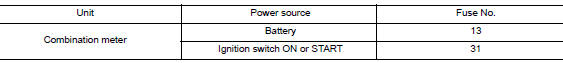
Is the fuse blown? YES >> Replace the blown fuse after repairing the affected circuit.
NO >> GO TO 2.
2.POWER SUPPLY CIRCUIT CHECK
1. Disconnect combination meter connector.
2. Check voltage between combination meter harness connector M77 terminals 45, 46 and ground.
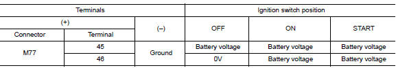
Is the inspection result normal? YES >> GO TO 3.
NO >> Repair or replace harness or connector.
3.GROUND CIRCUIT CHECK
- Turn ignition switch OFF.
- Check continuity between combination meter harness connector and ground.
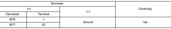
Is the inspection result normal? YES >> Inspection End.
NO >> Repair or replace harness or connector.
BCM (BODY CONTROL SYSTEM) (WITH INTELLIGENT KEY SYSTEM)
BCM (BODY CONTROL SYSTEM) (WITH INTELLIGENT KEY SYSTEM) : Diagnosis Procedure
Regarding Wiring Diagram information, refer to BCS-50, "Wiring Diagram".
1. CHECK FUSE
Check that the following fuse is not blown.

Is the fuse blown? YES >> Replace the blown fuse after repairing the affected circuit.
NO >> GO TO 2.
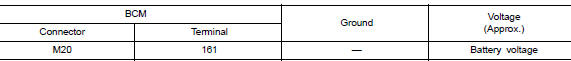
2. CHECK POWER SUPPLY CIRCUIT
- Disconnect BCM connector M20.
- Check voltage between BCM connector M20 and ground.
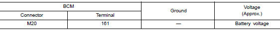
Is the inspection result normal? YES >> GO TO 3.
NO >> Repair or replace harness or connectors.
3. CHECK GROUND CIRCUIT
Check continuity between BCM connector M20 and ground.
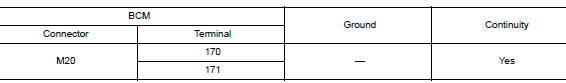
Is the inspection result normal? YES >> Inspection End.
NO >> Repair or replace harness or connectors.
BCM (BODY CONTROL SYSTEM) (WITHOUT INTELLIGENT KEY SYSTEM)
BCM (BODY CONTROL SYSTEM) (WITHOUT INTELLIGENT KEY SYSTEM) : Diagnosis Procedure
Regarding Wiring Diagram information, refer to BCS-110, "Wiring Diagram".
1. CHECK FUSE
Check that the following fuse is not blown.

Is the fuse blown? YES >> Replace the blown fuse after repairing the affected circuit.
NO >> GO TO 2.
2. CHECK POWER SUPPLY CIRCUIT
- Disconnect BCM connector M20.
- Check voltage between BCM connector M20 and ground.
Is the inspection result normal? YES >> GO TO 3.
NO >> Repair or replace harness or connectors.
3. CHECK GROUND CIRCUIT
Check continuity between BCM connector M20 and ground.
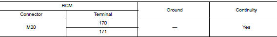
Is the inspection result normal? YES >> Inspection End.
NO >> Repair or replace harness or connectors.

 Meter buzzer circuit
Description
The buzzer for the warning chime system is installed in the combination
meter.
The combination meter sounds the buzzer based on the signals transmitted
from various units.
C ...
Other materials:
P0327, P0328 KS
DTC Description
DTC DETECTION LOGIC
DTC No.
CONSULT screen terms
(Trouble diagnosis content)
DTC detecting condition
P0327
KNOCK SEN/CIRC-B1
(Knock sensor 1 circuit low bank 1 or single
sensor)
An excessively low voltage from the knock sensor is sent to ECM.
...
U1000 CAN COMM circuit
Description
CAN (Controller Area Network) is a serial communication system for real time
application. It is an on-vehicle
multiplex communication system with high data communication speed and excellent
error detection ability.
Many electronic control units are equipped into vehicles, and ea ...
System
System Diagram
Compressor
Pressure relief valve
Liquid tank
Refrigerant pressure sensor
Condenser
Expansion valve
Evaporator
Blower motor
High-pressure gas
High-pressure liquid
Low-pressure liquid
Low-pressure gas
Suction port
Discharge port ...
