Nissan Rogue Service Manual: P0850 PNP switch
Description
Transmission range switch is turn ON when the selector lever is P or N.
ECM detects the position because the continuity of the line (the ON) exists.
DTC Description
DTC DETECTION LOGIC
| DTC No. | CONSULT screen terms (Trouble diagnosis content) | DTC detecting condition |
| P0850 | P-N POS SW/CIRCUIT (Park/neutral switch input circuit) | The signal of transmission range switch is not changed in the process of engine starting and driving. |
POSSIBLE CAUSE
- Harness or connectors (The transmission range switch circuit is open or shorted.)
- Transmission range switch
FAIL-SAFE
Not applicable
DTC CONFIRMATION PROCEDURE
1.INSPECTION START
Do you have CONSULT? Do you have CONSULT? YES >> GO TO 2.
NO >> GO TO 5.
2.PRECONDITIONING
If DTC Confirmation Procedure has been previously conducted, always perform the following procedure before conducting the next test.
- Turn ignition switch OFF and wait at least 10 seconds.
- Turn ignition switch ON.
- Turn ignition switch OFF and wait at least 10 seconds.
>> GO TO 3.
3.CHECK PNP SIGNAL FUNCTION
 With CONSULT
- Turn ignition switch ON.
- Select ÔÇťP/N POSI SWÔÇŁ in ÔÇťDATA MONITORÔÇŁ mode of ÔÇťENGINEÔÇŁ using CONSULT. Then check the ÔÇťP/N POSI SWÔÇŁ signal as per the following conditions.
| Selector lever position | Known-good signal |
| N or P position | ON |
| Except above position | OFF |
Is the inspection result normal? YES >> GO TO 4.
NO >> Proceed to EC-383, "Diagnosis Procedure".
4.PERFORM DTC CONFIRMATION PROCEDURE
- Select ÔÇťDATA MONITORÔÇŁ mode of ÔÇťENGINEÔÇŁ using CONSULT.
- Start engine and warm it up to normal operating temperature.
- Maintain the following conditions for at least 60 consecutive seconds.
CAUTION: Always drive vehicle at a safe speed.
| ENG SPEED | 1,000 - 6,375 rpm |
| COOLAN TEMP/S | More than 65┬░C (149┬░F) |
| B/FUEL SCHDL | 3.25 - 31.8 msec |
| VHCL SPEED SE | More than 64 km/h (40 mph) |
| Selector lever | Suitable position |
- Check 1st trip DTC.
Is 1st trip DTC detected? YES >> Proceed to EC-383, "Diagnosis Procedure".
NO >> INSPECTION END
5.PERFORM COMPONENT FUNCTION CHECK
- Turn ignition switch ON.
- Check the voltage between ECM harness connector terminals as per the following conditions.
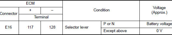
Is the inspection result normal? YES >> INSPECTION EN
NO >> Proceed to EC-383, "Diagnosis Procedure".
Diagnosis Procedure
1.CHECK TRANSMISSION RANGE SWITCH POWER SUPPLY
- Turn ignition switch OFF.
- Disconnect transmission range switch harness connector.
- Turn ignition switch ON.
- Check the voltage between transmission range switch harness connector and ground.
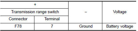
Is the inspection result normal? YES >> GO TO 3.
NO >> GO TO 2.
2.CHECK TRANSMISSION RANGE SWITCH POWER SUPPLY CIRCUIT
- Turn ignition switch OFF.
- Disconnect IPDM E/R harness connector.
- Check the continuity between transmission range switch harness connector and IPDM E/R harness connector.
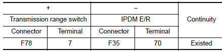
- Also check harness for short to ground.
Is the inspection result normal? YES >> Perform the trouble diagnosis for power supply circuit.
NO >> Repair or replace error-detected parts.
3.CHECK TRANSMISSION RANGE SWITCH SIGNAL CIRCUIT
- Turn ignition switch OFF.
- Disconnect ECM harness connector.
- Check the continuity between transmission range switch harness connector and ECM harness connector.
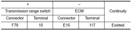
- Also check harness for short to ground and to power.
Is the inspection result normal? YES >> GO TO 4.
NO >> Repair or replace error-detected parts.
4.CHECK TRANSMISSION RANGE SWITCH
Check the transmission range switch. Refer to TM-111, "Component Inspection".
Is the inspection result normal? YES >> GO TO 5.
NO >> Replace transmission range switch. Refer to TM-220, "Removal and Installation".
5.CHECK INTERMITTENT INCIDENT
Refer to GI-41, "Intermittent Incident".
>> INSPECTION END
 P0643 sensor power supply
Description
ECM supplies a voltage of 5 V to some of the sensors systematically divided
into 2 groups, respectively.
Accordingly, when a short circuit develops in a sensor power source, a
malf ...
 P1078 EVT control position sensor
DTC Description
DTC DETECTION LOGIC
DTC No.
CONSULT screen terms
(Trouble diagnosis content)
DTC detecting condition
P1078
EXH TIM SEN/CIRC-B1
(EXH TIM SEN/CIRC-B1)
...
Other materials:
System description
VENTILATION SYSTEM
System Description
OUTLINE
Automatic A/C
The ventilation system is controlled by the A/C switch assembly. For details
of the automatic air conditioner
system, refer to HAC-10, "System Description".
Manual A/C
The ventilation system is controlled by the front air ...
Diagnosis system (BCM) (without intelligent key system)
COMMON ITEM
COMMON ITEM : CONSULT Function (BCM - COMMON ITEM)
APPLICATION ITEM
CONSULT performs the following functions via CAN communication with BCM.
Direct Diagnostic Mode
Description
Ecu Identification
The BCM part number is displayed.
Self Diagnostic ...
Symptom diagnosis
MULTI AV SYSTEM
Symptom Table
RELATED TO AUDIO
Symptoms
Check items
Probable malfunction location
The disk cannot be removed.
AV control unit
Malfunction in AV control unit.
Refer to AV-91, "On Board Diagnosis Function".
No sound comes ...
