Nissan Rogue Service Manual: P0078 EVT control solenoid valve
DTC Description
DTC DETECTION LOGIC
| DTC No. | CONSULT screen terms (Trouble diagnosis content) | DTC detecting condit |
| P0078 | EX V/T ACT/CIRC-B1 (Exhaust valve control solenoid circuit bank 1) | An improper voltage is sent to the ECM through exhaust valve timing control solenoid valve. |
POSSIBLE CAUSE
- Harness or connectors (Exhaust valve timing control solenoid valve circuit is open or shorted.)
- Exhaust valve timing control solenoid valve
FAIL-SAFE
Device fix mode
DTC CONFIRMATION PROCEDURE
1.PRECONDITIONING
If DTC Confirmation Procedure has been previously conducted, always perform the following procedure before conducting the next test.
- Turn ignition switch OFF and wait at least 10 seconds.
- Turn ignition switch ON.
- Turn ignition switch OFF and wait at least 10 seconds.
>> GO TO2.
2.PERFORM DTC CONFIRMATION PROCEDURE
- Start engine and let it idle for 5 seconds.
- Check 1st trip DTC.
Is 1st trip DTC detected? YES >> Proceed to EC-195, "Diagnosis Procedure".
NO >> INSPECTION END
Diagnosis Procedure
1.CHECK EXHAUST VALVE TIMING CONTROL SOLENOID VALVE POWER SUPPLY
- Turn ignition switch OFF.
- Disconnect exhaust valve timing (EVT) control solenoid valve harness connector.
- Turn ignition switch ON.
- Check the voltage between exhaust valve timing control solenoid valve harness connector and ground.
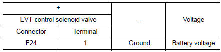
Is the inspection result normal? YES >> GO TO 3.
NO >> GO TO 2.
2.CHECK EXHAUST VALVE TIMING CONTROL SOLENOID VALVE POWER SUPPLY CIRCUIT
- Turn ignition switch OFF.
- Disconnect IPDM E/R harness connector.
- Check the continuity between EVT control solenoid valve harness connector and IPDM E/R harness connector.
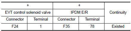
- Also check harness for short to ground.
Is the inspection result normal? YES >> Perform the trouble diagnosis for power supply circuit.
NO >> Repair or replace error-detected parts.
3.CHECK EXHAUST VALVE TIMING CONTROL SOLENOID VALVE GROUND CIRCUIT
- Turn ignition switch OFF.
- Disconnect ECM harness connector.
- Check the continuity between EVT control solenoid valve harness connector and ECM harness connector.
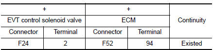
- Also check harness for short to ground and to power.
Is the inspection result normal? YES >> GO TO 4.
NO >> Repair or replace error-detected parts.
4.CHECK EXHAUST VALVE TIMING CONTROL SOLENOID VALVE
Check the exhaust valve timing control solenoid valve. Refer to EC-183, "Component Inspection".
Is the inspection result normal? YES >> GO TO 5.
NO >> Replace exhaust valve timing control solenoid valve.
5.CHECK INTERMITTENT INCIDENT
Refer to GI-41, "Intermittent Incident".
>> INSPECTION END
Component Inspection
1.CHECK EXHAUST VALVE TIMING CONTROL SOLENOID VALVE-1
- Turn ignition switch OFF.
- Disconnect exhaust valve timing control solenoid valve harness connector.
- Check resistance between exhaust valve timing control solenoid valve terminals as per the following.
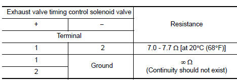
Is the inspection result normal?
YES >> GO TO 2.
NO >> Replace exhaust valve timing control solenoid valve. Refer to EM-44, "Exploded View".
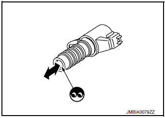
2.CHECK EXHAUST VALVE TIMING CONTROL SOLENOID VALVE-2
- Remove exhaust valve timing control solenoid valve. Refer to EM-44, "Exploded View".
- Provide 12 V DC between exhaust valve timing control solenoid valve terminals 1 and 2, and then interrupt it. Check that the plunger moves as shown in the figure.
CAUTION: Do not apply 12 V DC continuously for 5 seconds or more.
Doing so may result in damage to the coil in exhaust valve timing control solenoid valve.
NOTE: Always replace O-ring when exhaust valve timing control solenoid valve is removed.
Is the inspection result normal? YES >> INSPECTION END
NO >> Replace exhaust valve timing control solenoid valve. Refer to EM-44, "Exploded View".
 P0075 intake valve timing control
DTC Description
DTC DETECTION LOGIC
DTC No.
CONSULT screen terms
(Trouble diagnosis content)
DTC detecting condition
P0075
INT/V TIM V/CIR-B1
(Intake valve control sol ...
 P0101 MAF sensor
DTC Description
DTC DETECTION LOGIC
DTC No.
CONSULT screen terms
(Trouble diagnosis content)
DTC detecting condition
P0101
MAF SEN/CIRCUIT-B1
(Mass or volume air Flow ...
Other materials:
When traveling or registering your vehicle in
another country
When planning to drive your NISSAN vehicle
in another country, you should first find
out if the fuel available is suitable for your vehicle’s
engine.
Using fuel with an octane rating that is too low
may cause engine damage. All gasoline vehicles
must be operated with unleaded gasoline. The ...
Interior room lamp control system
Wiring Diagram
...
P1078 EVT control position sensor
DTC Description
DTC DETECTION LOGIC
DTC No.
CONSULT screen terms
(Trouble diagnosis content)
DTC detecting condition
P1078
EXH TIM SEN/CIRC-B1
(EXH TIM SEN/CIRC-B1)
An excessively high or low voltage from the sensor is sent to ECM.
POSSIBLE CAUSE
H ...
