Nissan Rogue Service Manual: Lower link
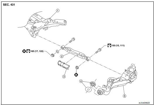
Exploded View

- Rear suspension member
- Lower link
- Lower link deflector
- Rubber washer (LH/RH)
- Rear suspension arm
 Front
Front
Removal and Installation
REMOVAL
- Remove wheel and tire using power tool. Refer to WT-60, "Exploded View".
- Remove connecting rod. Refer to RSU-21, "Exploded View".
- Remove rear height sensor (if equipped). Refer to EXL-271, "Removal and Installation - Rear Height Sensor".
- Set suitable jack under rear suspension arm to relieve the coil spring tension.
- Remove lower link, nut, and bolt from rear suspension arm with power tool.
- Remove lower link, nut, washer, and bolt from rear suspension member with power tool.
- Remove lower link protector (if necessary).
- Perform the inspection after removal. Refer to RSU-17, "Inspection".
INSTALLATION
Installation is in the reverse order of removal.
- Perform final tightening of rear suspension member and axle installation position under unladen conditions with tires on level ground.
- After installation, perform headlamp initialization. Refer to EXL-223, "Diagnosis Procedure".
- Adjust the neutral position of the steering angle sensor. Refer to BRC-70, "Work Procedure".
- Perform the inspection after installation. Refer to RSU-17, "Inspection".
Inspection
INSPECTION AFTER REMOVAL
Check lower link and bushing for any deformation, cracks, or damage. Replace it if necessary.
INSPECTION AFTER INSTALLATION
Check wheel alignment. Refer to RSU-6, "Inspection".
 Rear suspension ARM
Exploded View
Rear suspension arm
Rubber washer (LH/RH)
Rear suspension arm bracket
Rear suspension arm stay
Front
Removal and Installation
REMOVAL
Remove the wheel hu ...
 Upper link
Exploded View
Rear suspension member
Upper link
Rubber washer (LH/RH)
Rear suspension arm
Front
Removal and Installation
REMOVAL
Remove wheel and tir ...
Other materials:
CAN system (type 5)
MAIN LINE BETWEEN IPDM-E AND DLC CIRCUIT
Diagnosis Procedure
1.CHECK CONNECTOR
Turn the ignition switch OFF.
Disconnect the battery cable from the negative terminal.
Check the following terminals and connectors for damage, bend and
loose connection (connector side
an ...
Parking/parking on hills
Parking/parking on hills
WARNING
Do not stop or park the vehicle over
flammable materials such as dry grass,
waste paper or rags. They may ignite
and cause a fire.
Safe parking procedures require that
both the parking brake be set and the
transmiss ...
B142A ignition voltage
Description
DTC B142A IGNITION VOLTAGE
Ignition voltage is supplied to the air bag diagnosis sensor unit when the
ignition is in the ON position. The air
bag diagnosis sensor unit will monitor for low or high ignition voltage.
PART LOCATION
Refer to SRC-6, "Component Parts Location" ...
