Nissan Rogue Service Manual: Headlining
Exploded View
WITHOUT MOONROOF
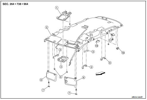
- Map lamp assembly bracket
- Headlining
- Assist grip (without coat hanger)
- Map lamp assembly
- Sun visor holder (LH/RH)
- Sun visor (RH)
- Sun visor cover
- Sun visor (LH)
- Headlining cover
- Assist grip (with coat hanger)
- Top tether strap child restraint finisher
 Front
Front
 Pawl
Pawl
WITH MOONROOF
- Headlining
- Front assist grip bracket (LH)
- Map lamp assembly bracket
- Front assist grip bracket (RH)
- Assist grip (with coat hanger)
- Map lamp assembly
- Assist grip (without coat hanger)
- Sun visor holder (LH/RH)
- Sun visor (RH)
- Sun visor cover (LH/RH)
- Sun visor (LH)
- Headlining cover
- Top tether strap child restraint finisher
Front
Pawl
Removal and Installation
REMOVAL
WARNING: Before servicing the SRS, turn ignition switch OFF, disconnect both battery terminals then wait at least three minutes.
- Disconnect negative and positive battery terminals, then wait at least three minutes. Refer to PG-77, "Removal and Installation".
- Remove front pillar finisher (LH/RH). Refer to INT-20, "FRONT PILLAR FINISHER : Removal and Installation".
- Remove center pillar upper finisher (LH/RH). Refer to INT-21, "CENTER PILLAR UPPER FINISHER : Removal and Installation".
- Remove luggage side upper finisher (LH/RH). Refer to INT-36, "LUGGAGE SIDE UPPER FINISHER : Removal and Installation".
- Remove map lamp assembly. Refer to INL-55, "Removal and Installation".
- Disconnect map lamp assembly, personal lamp and microphone harness connectors.
- Remove luggage side upper finisher (LH/RH). Refer to INT-36, "LUGGAGE SIDE UPPER FINISHER : Removal and Installation".
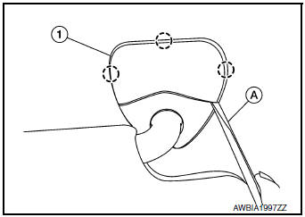
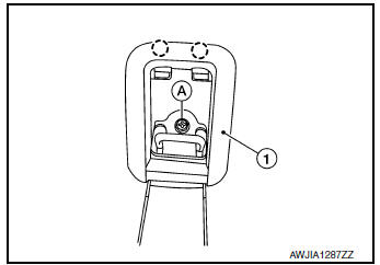
- Remove sun visor cover (LH/RH) (1) by inserting a suitable tool (A) as shown.
: Pawl
CAUTION: Do not damage headlining or sun visor cover surface.
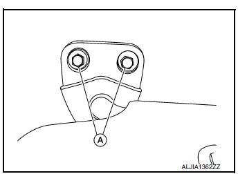
- Remove sun visor screws (A) (LH/RH), then disconnect harness connectors and remove .
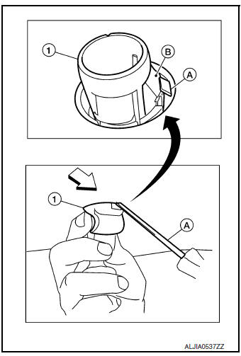
- Insert a suitable tool (A) at approximately a 30 degree angle into the sun visor holder notch on the front of the sun visor holder (1). Press in to release the locking tab (B). While holding in locking tab (B), turn the sun visor holder (1) 90 degrees to release it from the headliner.
- If the sun visor holder (1) does not fully rotate, make sure that the suitable tool (A) is pressing in on the locking tab (B) and is not positioned under locking tab (B). Reinsert the suitable tool (A) as necessary to release the locking tab (B).
- Front
CAUTION: Do not force the sun visor holder when removing as the locking tab may be damaged if the suitable tool is not positioned correctly.
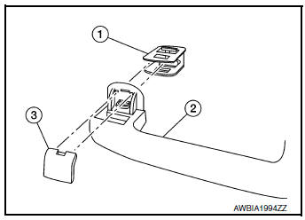
- Remove front assist grip (LH/RH) and rear assist grip (LH/RH).
- Remove assist grip cap (3).
- Release clip (1) and remove assist grip (2).
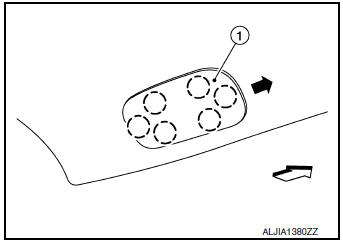
- Insert suitable tool from front, release pawls then pull headlining cover (1) forward and outward to remove.
 : Pawl
 Front
Front
- Insert two fingers through hole on headlining.
(A) :Tether
- Release tether (A) from hook (B) and remove.
- Remove screw (A) then release pawls using a suitable tool and
remove child tether finisher (1).: Pawl
- Release headlining clip at rear and remove headlining through the back door.
CAUTION:
- When removing headlining, two workers are required.
- Do not bend headlining when removing.
- Be careful not to scratch or damage any part of the body while removing the headlining.
INSTALLATION
Installation is in the reverse order of removal.
CAUTION:
- Install sun-visor holder (LH/RH) and clips of the rear of headlining for positioning.
- Do not to bend the headlining when installing.
 Floor trim
Exploded View
Rear floor trim (with third row
seat)
Rear floor trim (without third
row seat)
Floor trim hook
Front floor trim
Front floor spacer (RH)
Front floor sp ...
 Luggage trim
Exploded View
WITH THIRD ROW SEAT
Tonneau cover (if equipped)
Strap (LH/RH)
Luggage floor finisher (RH)
Luggage floor center finisher
Luggage floor finisher (LH) ...
Other materials:
Starting the engine (models without NISSAN
Intelligent Key® system)
Apply the parking brake.
Move the shift lever to P (Park) or N (Neutral).
P (Park) is recommended.
The shift lever cannot be moved out of
P (Park) and into any of the other gear
positions if the ignition key is turned to
the OFF position or if the key is removed
from the ignition ...
Removal and installation
REAR WHEEL HUB
Exploded View
Suspension arm
Back plate
Wheel stud
Wheel hub and bearing
Disc brake rotor
Plug
Removal and Installation
REMOVAL
Wheel Hub and Bearing
Remove the wheel and tire using power tool. Refer to WT-57,
"Adjustment".
Remove t ...
B0098 front door satellite sensor RH
DTC Logic
DTC DETECTION LOGIC
With CONSULT
CONSULT name
DTC
DTC detecting condition
Repair order
DOOR SATELLITE SENSOR RH
[SENSOR FAIL]
B0098
Front door satellite sensor RH has malfunctioned.
Refer to SRC-72, "Diagnosis Procedure".
...
