Nissan Rogue Service Manual: Removal and installation
REAR WHEEL HUB
Exploded View
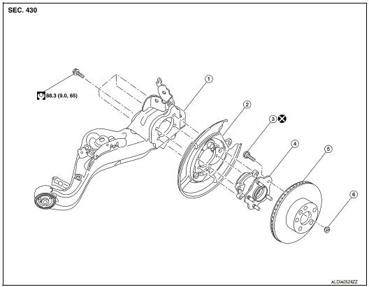
- Suspension arm
- Back plate
- Wheel stud
- Wheel hub and bearing
- Disc brake rotor
- Plug
Removal and Installation
REMOVAL
Wheel Hub and Bearing
- Remove the wheel and tire using power tool. Refer to WT-57, "Adjustment".
- Remove the bolt and separate the rear wheel sensor from the wheel hub and bearing. Refer to BRC-133, "REAR WHEEL SENSOR : Exploded View".
CAUTION:
- Failure to separate the rear wheel sensor from the wheel hub and bearing may result in damage to the rear wheel sensor.
- Pull out the rear wheel sensor, being careful to turn it as little as possible. Do not pull on wheel sensor harness.
- Remove torque member bolts using power tool, leaving the brake
hose attached. Position brake caliper
aside with wire. Refer to BR-42, "BRAKE CALIPER ASSEMBLY : Exploded View".
CAUTION: Do not depress brake pedal while brake caliper is removed.
- Put alignment marks on the disc brake rotor and on the wheel hub and
bearing. Remove the disc brake
rotor. Remove disc brake rotor.
CAUTION: Do not drop disc brake rotor.
- Remove the hub bolts and the wheel hub and bearing.
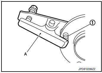
- If necessary, remove the wheel studs (1) from the wheel hub and bearing using a suitable tool (A).
CAUTION:
- Remove the wheel studs only when necessary.
- Do not hammer the wheel studs or damage to the wheel hub and bearing may occur.
- Pull out the wheel studs in a direction perpendicular to the wheel hub and bearing.
- Inspect the components. Refer to RAX-8, "Inspection".
INSTALLATION
Installation is in the reverse order of removal.
- Place a washer (A) as shown to install the wheel studs (1) by using the tightening force of the nut (B).
CAUTION:
- Do not reuse the wheel stud.
- Check that there is no clearance between the wheel stud and the wheel hub and bearing.
- Before installing, make sure there is no foreign material such as iron fragments adhered to the pick-up part of the rear wheel sensor.
- When installing, make sure there is no foreign material such as iron fragments on and in the hole in the wheel hub and bearing for the rear wheel sensor. Make sure no foreign material has been caught in the sensor rotor. Remove any foreign material and clean the mount.
- Install the rear wheel sensor to the wheel hub and bearing. Refer to BRC-133, "REAR WHEEL SENSOR : Exploded View".
- Align the matching marks made during removal when reusing the disc brake rotor.
- Check that the wheel hub and bearing operates smoothly.
- Perform the inspection after installation. Refer to RAX-8, "Inspection".
Inspection
INSPECTION AFTER REMOVAL
Check wheel hub and bearing for wear, cracks, and damage. Replace if necessary.
INSPECTION AFTER INSTALLATION
- Adjust parking brake operation (stroke). Refer to PB-4, "Inspection and Adjustment".
- Check wheel alignment. Refer to RSU-6, "Inspection".
- Adjust neutral position of steering angle sensor. Refer to BRC-70, "Work Procedure".
 Periodic maintenance
REAR WHEEL HUB AND HOUSING
Inspection
INSPECTION
Make sure the conditions (looseness, back lash) of each component and
component conditions (wear, damage)
are normal.
WHEEL HUB AND BEARING INSP ...
 Service data and specifications (SDS)
Wheel Bearing
...
Other materials:
Fuel tank
FWD
FWD : Exploded View
Fuel filler cap
Grommet
Fuel filler tube
Cover
Clamp
Fuel filler hose
Clamp
Vent hose
Fuel tank protector
Fuel tank strap (LH)
Fuel tank strap (RH)
Fuel tank
T ...
U1010 control unit (CAN)
Description
Initial diagnosis of combination meter.
DTC Logic
DTC DETECTION LOGIC
DTC
CONSULT
Detection Condition
Possible Cause
U1010
CONTROL UNIT (CAN)
[U1010]
When detecting error during the initial diagnosis of the CAN
controller
of co ...
Fluid cooler hose
Exploded View
COMPONENT PARTS LOCATION
Transaxle assembly
Fluid cooler hose A
Hose clamp
Fluid cooler hose B
CVT oil warmer
To radiator
: Always replace after every
disassembly.
Removal and Installation
REMOVAL
NOTE:
When removing components such as hoses, tubes/lines, ...
