Nissan Rogue Service Manual: Fluid cooler hose
Exploded View
COMPONENT PARTS LOCATION
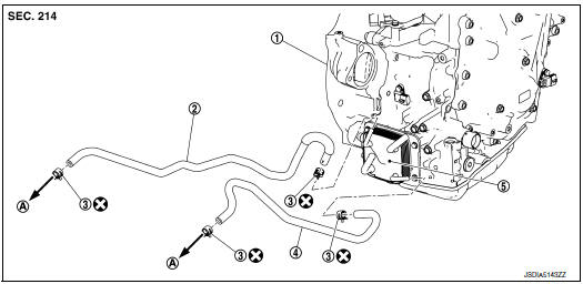
- Transaxle assembly
- Fluid cooler hose A
- Hose clamp
- Fluid cooler hose B
- CVT oil warmer
- To radiator
 : Always replace after every
disassembly.
: Always replace after every
disassembly.
Removal and Installation
REMOVAL
NOTE: When removing components such as hoses, tubes/lines, etc., cap or plug openings to prevent fluid from spilling.
- Remove engine under cover. Refer to EXT-37, "ENGINE UNDER COVER : Removal and Installation".
- Remove fender protector side cover. Refer to EXT-28, "FENDER PROTECTOR : Exploded View".
- Remove fluid cooler hoses.
INSTALLATION
Installation is in the reverse order of removal.
CAUTION:
- Do not reuse hose clamp.
- Securely install fluid cooler hose A clip to the radiator core support.
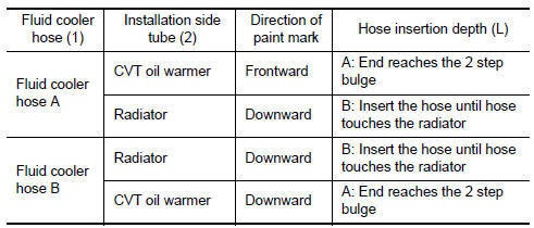
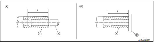
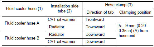
- Refer to the followings when installing fluid cooler hoses.
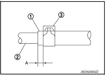
- Refer to the followings when installing hose clamps.
CAUTION: Hose clamp should not interfere with the bulge of tube.
Inspection
INSPECTION AFTER INSTALLATION
Check for CVT fluid leakage and check CVT fluid level. Refer to TM-190, "Inspection".
 Water hose
Exploded View
Water outlet
Hose clamp
Water hose A
Clip
CVT oil warmer
Transaxle assembly
Water hose B
Heater thermostat
Water hose C
: Always replace after every
di ...
 CVT oil warmer
Exploded View
Transaxle assembly
CVT oil warmer
: N·m (kg-m, in-lb)
Removal and Installation
REMOVAL
WARNING:
Do not remove the radiator cap when the engine is hot. Serious burns co ...
Other materials:
U1000 CAN COMM circuit
DTC Logic
DTC DETECTION LOGIC
DTC
CONSULT
Detection Condition
Possible Cause
U1000
CAN COMM CIRC
[U1000]
When combination meter is not transmitting or receiving CAN
communication signals for 2 seconds or more.
CAN communication system
D ...
Oil
Description
MAINTENANCE OF OIL LEVEL
The compressor oil is circulating in the system together with the
refrigerant. It is necessary to fill compressor
with oil when replacing A/C system parts or when a large amount of refrigerant
leak is detected. It is important
to always maintain oil level ...
Windshield-washer fluid
Windshield-washer fluid reservoir
Fill the windshield-washer fluid reservoir periodically.
Add windshield-washer fluid when the low
windshield-washer fluid warning light comes on.
To fill the windshield-washer fluid reservoir, lift
the cap off the reservoir and pour the windshieldwasher ...
