Nissan Rogue Service Manual: Front passenger air bag module
Exploded View
- Front passenger air bag module
- Steering member
Removal and Installation
WARNING:
- Before servicing the SRS, turn ignition switch OFF, disconnect both battery terminals then wait at least three minutes.
- Always work from the side of air bag module. Do not work in front of it.
- Do not use air tools or electric tools for servicing.
REMOVAL
- Remove the Instrument panel assembly. Refer to IP-14, "INSTRUMENT PANEL ASSEMBLY : Removal and Installation".
- Remove front passenger air bag module screws.
- Release the pawls by removing the front passenger air bag module (1) as shown.
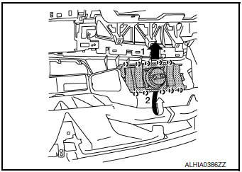
 : Pawl
CAUTION:
- Always place the front passenger air bag module with pad side facing upward as shown.
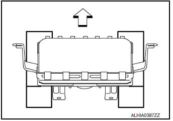
 : Upward
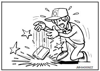
- Replace the front passenger air bag module if it has been dropped or sustained an impact.
- Do not strike the front passenger air bag module.
- Do not insert any foreign objects (screwdriver, etc.) into the passenger air bag module.
- Do not disassemble the passenger air bag module.
- Do not expose the passenger air bag module to temperatures exceeding 90°C (194°F).
- Do not allow oil, grease, detergent, or water to come in contact with the front passenger air bag module.
INSTALLATION
Note the following items, and then install in the reverse order of removal.
CAUTION:
- Do not reuse the front passenger air bag module bolts.
- Do not damage the front passenger air bag module harness during installation.
- After installation is complete, check that no system malfunction is detected causing the air bag warning lamp to illuminate.
- If a malfunction is indicated by the air bag warning lamp after repair or replacement of the malfunctioning parts, perform the SRS final check. Refer to SRC-18, "Trouble Diagnosis with CONSULT".
 Spiral cable
Exploded View
Combination switch
Steering angle sensor
Spiral cabl
Removal and Installation
WARNING:
Before servicing the SRS, turn ignition switch OFF, disconnect
both ...
 Side curtain air bag module
Exploded View
Side curtain air bag module
Fron
Removal and Installation
WARNING:
Before servicing the SRS, turn ignition switch OFF, disconnect
both battery terminals then ...
Other materials:
Back door finisher
Exploded View
Back door
Access cover
Back door finisher
Clip
Pawl
Metal clip
Removal and Installation
REMOVAL
Using a suitable tool (A) release upper LH most clip, then
release remaining clips by gently pulling down on back door finisher
(1).
: Clip
INSTA ...
P2765 input speed sensor B
DTC Description
DTC DETECTION LOGIC
DTC
CONSULT screen terms
(Trouble diagnosis content)
DTC detection condition
P2765
INPUT SPEED SENSOR B
(Input/Turbine Speed Sensor B Circuit)
When 1 is satisfied and any of 2, 3 or 4 is satisfied and this state
is maintaine ...
Sensor power supply2 circuit
Description
ECM supplies a voltage of 5 V to some of the sensors systematically divided
into 2 groups, respectively.
Accordingly, when a short circuit develops in a sensor power source, a
malfunction may occur simultaneously
in the sensors belonging to the same group as the short-circuited ...
