Nissan Rogue Service Manual: DTC/circuit diagnosis
U0121 VDC CAN 2
DTC Logic
DTC DETECTION LOGIC
NOTE: If DTC U0121 is displayed with DTC U1000, first perform the trouble diagnosis for DTC U1000. Refer to DAS- 106, "DISTANCE SENSOR : DTC Logic".
|
CONSULT Display |
DTC Detection Condition |
Possible Cause |
| VDC CAN CIR1 [U0121] | Distance sensor receives an error signal from ABS actuator and electric unit (control unit) via CAN communication. |
|
DTC CONFIRMATION PROCEDURE
1.PERFORM SELF DIAGNOSTIC RESULT
- Start the engine.
- Perform тАЬSelf Diagnostic ResultтАЭ of тАЬLASER/RADARтАЭ using CONSULT.
Is display history of DTC U0121 CRNT? YES >> Refer to DAS-99, "Diagnosis Procedure".
NO >> Refer to GI-41, "Intermittent Incident".
Diagnosis Procedure
1.CHECK ABS ACTUATOR AND ELECTRIC UNIT (CONTROL UNIT) SELF DIAGNOSTIC RESULT
Perform тАЬSelf Diagnostic ResultтАЭ of тАЬABSтАЭ using CONSULT.
Are any DTCs detected? YES >> Refer to BRC-55, "DTC Index".
NO >> Replace the distance sensor. Refer to DAS-160, "Removal and Installation".
U0122 VDC P-RUN DIAG
DTC Logic
DTC DETECTION LOGIC
|
CONSULT Display |
DTC Detection Condition |
Possible Cause |
| VDC CAN CIR1(LDP) [U0122] | Around view monitor control unit receives incorrect signal (P-RUN) from ABS actuator and electric unit (control Unit) via CAN communication. |
|
DTC CONFIRMATION PROCEDURE
1.PERFORM SELF DIAGNOSTIC RESULT
- Turn ignition ON.
- Perform тАЬSelf Diagnostic ResultтАЭ of тАЬAVMтАЭ using CONSULT.
Is DTC detected? YES >> Refer to DAS-100, "Diagnosis Procedure".
NO >> Refer to GI-41, "Intermittent Incident".
Diagnosis Procedure
1.CHECK ABS ACTUATOR AND ELECTRIC UNIT (CONTROL UNIT) SELF DIAGNOSTIC RESULT
Perform тАЬSelf Diagnostic ResultтАЭ of тАЬABSтАЭ using CONSULT.
Are any DTCs detected? YES >> Refer to BRC-55, "DTC Index".
NO >> Replace the around view monitor control unit. Refer to DAS-163, "Removal and Installation".
U0126 STRG SEN CAN 1
DTC Logic
DTC DETECTION LOGIC
NOTE: If DTC U0126 is displayed with DTC U1000, first perform the trouble diagnosis for DTC U1000. Refer to DAS- 106, "DISTANCE SENSOR : DTC Logic".
|
CONSULT Display |
DTC Detection Condition |
Possible Cause |
| ST ANG SEN SIG [U0126] | Distance sensor receives an error signal from steering angle sensor via CAN communication. |
|
DTC CONFIRMATION PROCEDURE
1.PERFORM SELF DIAGNOSTIC RESULT
- Start the engine.
- Perform тАЬSelf Diagnostic ResultтАЭ of тАЬLASER/RADARтАЭ using CONSULT.
Is DTC detected? YES >> Refer to DAS-101, "Diagnosis Procedure".
NO >> Refer to GI-41, "Intermittent Incident".
Diagnosis Procedure
1.CHECK ABS ACTUATOR AND ELECTRIC UNIT (CONTROL UNIT) SELF DIAGNOSTIC RESULT
Perform тАЬSelf Diagnostic ResultтАЭ of тАЬABSтАЭ using CONSULT.
Are any DTCs detected? YES >> Refer to BRC-55, "DTC Index".
NO >> Replace the distance sensor. Refer to DAS-160, "Removal and Installation".
U0401 ECM CAN 1
DTC Logic
DTC DETECTION LOGIC
NOTE: If DTC U0401 is displayed with DTC U1000, first perform the trouble diagnosis for DTC U1000. Refer to DAS- 106, "DISTANCE SENSOR : DTC Logic".
|
CONSULT Display |
DTC Detection Condition |
Possible Cause |
| ECM CAN CIR2 [U0401] | Distance sensor receives an error signal from ECM via CAN communication. |
|
DTC CONFIRMATION PROCEDURE
1.PERFORM SELF DIAGNOSTIC RESULT
- Start the engine.
- Perform тАЬSelf Diagnostic ResultтАЭ of тАЬLASER/RADARтАЭ using CONSULT.
Is DTC detected? YES >> Refer to DAS-102, "Diagnosis Procedure".
NO >> Refer to GI-41, "Intermittent Incident".
Diagnosis Procedure
1.CHECK ECM SELF DIAGNOSTIC RESULT
Perform тАЬSelf Diagnostic ResultтАЭ of тАЬENGINEтАЭ using CONSULT.
Are any DTCs detected? YES >> Refer to EC-93, "DTC Index".
NO >> Replace the distance sensor. Refer to DAS-160, "Removal and Installation".
U0415 VDC CAN 1
DTC Logic
DTC DETECTION LOGIC
NOTE: If DTC U0415 is displayed with DTC U1000, first perform the trouble diagnosis for DTC U1000. Refer to DAS- 106, "DISTANCE SENSOR : DTC Logic".
|
CONSULT Display |
DTC Detection Condition |
Possible Cause |
| VDC CAN CIR2 [U0415] | Distance sensor receives an error signal from ABS actuator and electric unit (control unit) via CAN communication. |
|
DTC CONFIRMATION PROCEDURE
1.PERFORM SELF DIAGNOSTIC RESULT
- Start the engine.
- Perform тАЬSelf Diagnostic ResultтАЭ of тАЬLASER/RADARтАЭ using CONSULT.
Is display history of DTC U0415 CRNT? YES >> Refer to DAS-103, "Diagnosis Procedure".
NO >> Refer to GI-41, "Intermittent Incident".
Diagnosis Procedure
1.CHECK ABS ACTUATOR AND ELECTRIC UNIT (CONTROL UNIT) SELF DIAGNOSTIC RESULT
Perform тАЬSelf Diagnostic ResultтАЭ of тАЬABSтАЭ using CONSULT.
Are any DTCs detected? YES >> Refer to BRC-55, "DTC Index".
NO >> Replace the distance sensor. Refer to DAS-160, "Removal and Installation".
U0416 VDC CHECKSUM DIAG
DTC Logic
DTC DETECTION LOGIC
|
CONSULT Display |
DTC Detection Condition |
Possible Cause |
| VDC CAN CIR2(LDP) [U0416] | Around view monitor control unit receives incorrect signal (P-RUN) from ABS actuator and electric unit (control unit) via CAN communication. |
|
DTC CONFIRMATION PROCEDURE
1.PERFORM SELF DIAGNOSTIC RESULT
- Turn ignition ON.
- Perform тАЬSelf Diagnostic ResultтАЭ of тАЬAVMтАЭ using CONSULT.
Are any DTCs displayed? YES >> Refer to DAS-104, "Diagnosis Procedure".
NO >> Refer to GI-41, "Intermittent Incident".
Diagnosis Procedure
1.CHECK ABS ACTUATOR AND ELECTRIC UNIT (CONTROL UNIT) SELF DIAGNOSTIC RESULT
Perform тАЬSelf Diagnostic ResultтАЭ of тАЬABSтАЭ using CONSULT.
Are any DTCs detected? YES >> Refer to BRC-55, "DTC Index".
NO >> Replace the around view monitor control unit. Refer to DAS-163, "Removal and Installation".
U0428 STEERING ANGLE SENSOR
AROUND VIEW MONITOR CONTROL UNIT
AROUND VIEW MONITOR CONTROL UNIT : DTC Logic
DTC DETECTION LOGIC
|
CONSULT Display |
DTC Detection Condition |
Possible Cause |
| ST ANG SEN CALIB [U0428] | Predictive course line center position adjustment of steering angle sensor is incomplete. | Adjust predictive course line center position adjustment of steering angle sensor. |
AROUND VIEW MONITOR CONTROL UNIT : Diagnosis Procedure
1.ADJUST PREDICTIVE COURSE LINE CENTER POSITION ADJUSTMENT OF STEERING ANGLE SENSOR
When U0428 is detected, the predictive course line center position of steering angle sensor needs to be adjusted.
>> Adjust the predictive course line center position of steering angle sensor. Refer to AV-291, "PREDICTED COURSE LINE CENTER POSITION ADJUSTMENT : Work Procedure".
DISTANCE SENSOR
DISTANCE SENSOR : DTC Logic
DTC DETECTION LOGIC
|
CONSULT Display |
DTC Detection Condition |
Possible Cause |
| ST ANG SEN CALIB [U0428] | Predictive course line center position adjustment of steering angle sensor is incomplete. | Adjust predictive course line center position adjustment of steering angle sensor. |
DISTANCE SENSOR : Diagnosis Procedure
1.ADJUST PREDICTIVE COURSE LINE CENTER POSITION ADJUSTMENT OF STEERING ANGLE SENSOR
When U0428 is detected, the predictive course line center position of steering angle sensor needs to be adjusted.
>> Adjust the predictive course line center position of steering angle sensor. Refer to DAS-88, "Work Procedure".
U1000 CAN COMM CIRCUIT
AROUND VIEW MONITOR CONTROL UNIT
AROUND VIEW MONITOR CONTROL UNIT : DTC Logic
DTC DETECTION LOGIC
|
CONSULT Display |
DTC Detection Condition |
Possible Cause |
| CAN COMM CIRCUIT [U1000] | Around view monitor control unit is not transmitting or receiving CAN communication signal for 2 seconds or more. | CAN communication system. |
AROUND VIEW MONITOR CONTROL UNIT : Diagnosis Procedure
1.PERFORM SELF DIAGNOSTIC RESULT
- Turn ignition switch ON and wait for 2 seconds or more.
- Perform тАЬSelf Diagnostic ResultтАЭ for тАЬAVMтАЭ.
Is CAN COMM CIRCUIT displayed? YES >> Refer to LAN-17, "Trouble Diagnosis Flow Chart".
NO >> Refer to GI-41, "Intermittent Incident".
DISTANCE SENSOR
DISTANCE SENSOR : DTC Logic
DTC DETECTION LOGIC
|
CONSULT Display |
DTC Detection Condition |
Possible Cause |
| CAN COMM CIRCUIT [U1000] | Distance sensor is not transmitting or receiving CAN communication signal for 2 seconds or more. | CAN communication system. |
DISTANCE SENSOR : Diagnosis Procedure
1.PERFORM SELF DIAGNOSTIC RESULT
- Turn ignition switch ON and wait for 2 seconds or more.
- Perform тАЬSelf Diagnostic ResultтАЭ for тАЬLASER/RADARтАЭ
Is CAN COMM CIRCUIT displayed? YES >> Refer to LAN-17, "Trouble Diagnosis Flow Chart".
NO >> Refer to GI-41, "Intermittent Incident".
U1010 CONTROL UNIT (CAN)
AROUND VIEW MONITOR CONTROL UNIT
AROUND VIEW MONITOR CONTROL UNIT : DTC Logic
DTC DETECTION LOGIC
|
CONSULT Display |
DTC Detection Condition |
Possible Cause |
| CONTROL UNIT (CAN) [U1010] | Error during CAN controller hardware initialization (VCAN). | Replace the Around view monitor control unit if
the malfunction occurs constantly.
Refer to AV-387, "Removal and Installation". |
DISTANCE SENSOR
DISTANCE SENSOR : DTC Logic
DTC DETECTION LOGIC
|
CONSULT Display |
DTC Detection Condition |
Possible Cause |
| CONTROL UNIT (CAN) [U1010] | Error during CAN controller hardware initialization (VCAN). | Replace the distance sensor if the malfunction
occurs constantly.
Refer to DAS-160, "Removal and Installation". |
U111A REAR CAMERA IMAGE SIGNAL CIRCUIT
DTC Logic
DTC DETECTION LOGIC
|
CONSULT Display |
DTC Detection Condition |
Possible Cause |
| Rear display output signal diagnosis (Harness disconnection) [U111A] | Rear view camera image signal circuit open or short. | Check rear view camera image signal circuit. |
Diagnosis Procedure
Regarding Wiring Diagram information, refer to DAS-53, "Wiring Diagram".
1.CHECK REAR VIEW CAMERA POWER SUPPLY AND GROUND CIRCUIT CONTINUITY
- Turn ignition switch OFF.
- Disconnect around view monitor control unit and rear view camera connectors.
- Check continuity between around view monitor control unit connector M114 and rear view camera connector D514.
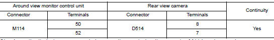
- Check continuity between around view monitor control unit connector M114 and ground.
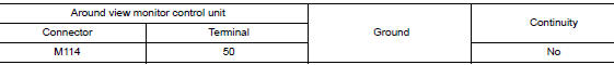
Is the inspection result normal? YES >> GO TO 2.
NO >> Repair or replace harness or connectors.
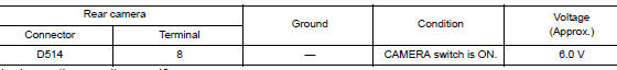
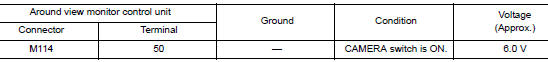
2.CHECK REAR VIEW CAMERA POWER SUPPLY VOLTAGE
- Connect around view monitor control unit and rear view camera connectors.
- Turn ignition switch ON.
- Check voltage between around view monitor control unit connector M114 and ground.
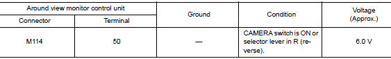
Is the inspection result normal? YES >> GO TO 3.
NO >> Replace around view monitor control unit. Refer to DAS-163, "Removal and Installation".
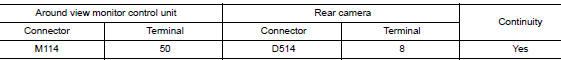
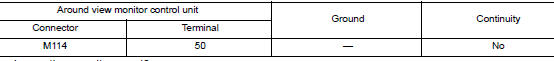
3.CHECK REAR VIEW CAMERA IMAGE SIGNAL AND IMAGE SIGNAL GROUND CIRCUIT CONTINUITY
- Turn ignition switch OFF.
- Disconnect around view monitor control unit and rear view camera connectors.
- Check continuity between around view monitor control unit connector M114 and rear view camera connector D514.
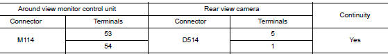
- Check continuity between around view monitor control unit connector M114 and ground.
Is the inspection result normal? YES >> GO TO 4.
NO >> Repair or replace harness or connectors.
4.CHECK REAR VIEW CAMERA IMAGE SIGNAL
- Connect around view monitor control unit and rear view camera connectors.
- Turn ignition switch ON.
- Check signal between the terminals of around view monitor control unit connector M114.
Is the inspection result normal? YES >> Replace around view monitor control unit. Refer to DAS-163, "Removal and Installation".
NO >> Replace rear view camera. Refer to DAS-166, "Removal and Installation".
U111B SIDE CAMERA RH IMAGE SIGNAL CIRCUIT
DTC Logic
DTC DETECTION LOGIC
|
CONSULT Display |
DTC Detection Condition |
Possible Cause |
| Right side display output signal diagnosis (Harness disconnection) [U111B] | Right side camera image signal circuit open or short. | Check right side camera image signal circuit. |
Diagnosis Procedure
Regarding Wiring Diagram information, refer to DAS-53, "Wiring Diagram".
1.CHECK RH SIDE CAMERA POWER SUPPLY AND GROUND CIRCUIT CONTINUITY
- Turn ignition switch OFF.
- Disconnect around view monitor control unit and RH side camera connectors.
- Check continuity between around view monitor control unit connector M114 and RH side camera connector D107.
- Check continuity between around view monitor control unit connector M114 and ground.
Is the inspection result normal? YES >> GO TO 2.
NO >> Repair or replace harness or connectors.
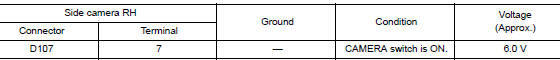
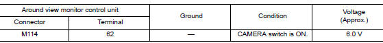
2.CHECK RH SIDE CAMERA POWER SUPPLY VOLTAGE
- Connect around view monitor control unit and RH side camera connectors.
- Turn ignition switch ON.
- Check voltage between around view monitor control unit connector M114 and ground.
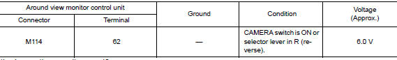
Is the inspection result normal? YES >> GO TO 3.
NO >> Replace around view monitor control unit. Refer to DAS-163, "Removal and Installation".
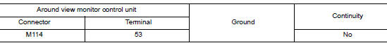
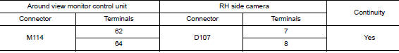
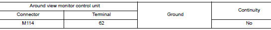
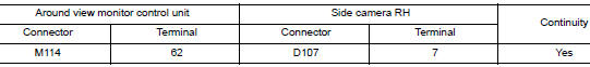
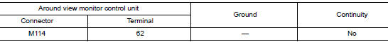
3.CHECK RH SIDE CAMERA IMAGE SIGNAL AND IMAGE SIGNAL GROUND CIRCUIT CONTINUITY
- Turn ignition switch OFF.
- Disconnect around view monitor control unit and RH side camera connectors.
- Check continuity between around view monitor control unit connector M114 and RH side camera connector D107.
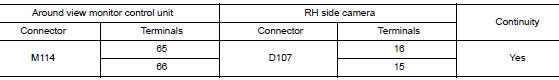
- Check continuity between around view monitor control unit connector M114 and ground.
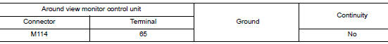
Is the inspection result normal? YES >> GO TO 4.
NO >> Repair or replace harness or connectors.
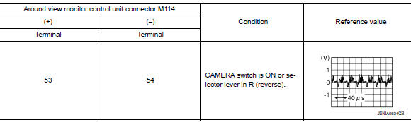
4.CHECK RH SIDE CAMERA IMAGE SIGNAL
- Connect around view monitor control unit and RH side camera connectors.
- Turn ignition switch ON.
- Check signal between the terminals of around view monitor control unit connector M114.
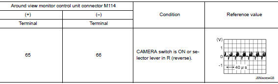
Is the inspection result normal? YES >> Replace around view monitor control unit. Refer to DAS-163, "Removal and Installation".
NO >> Replace RH side camera. Refer to DAS-161, "Removal and Installation".
U111C FRONT CAMERA IMAGE SIGNAL CIRCUIT
DTC Logic
DTC DETECTION LOGIC
|
CONSULT Display |
DTC Detection Condition |
Possible Cause |
| Front display output signal diagnosis (Harness disconnection) [U111C] | Front camera image signal circuit open or short. | Check front camera image signal circuit. |
Diagnosis Procedure
Regarding Wiring Diagram information, refer to DAS-53, "Wiring Diagram".
1.CHECK FRONT CAMERA POWER SUPPLY AND GROUND CIRCUIT CONTINUITY
- Turn ignition switch OFF.
- Disconnect around view monitor control unit and front camera connectors.
- Check continuity between around view monitor control unit connector M114 and front camera connector E226.
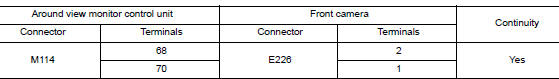
- Check continuity between around view monitor control unit connector M114 and ground.
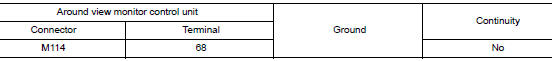
Is the inspection result normal? YES >> GO TO 2.
NO >> Repair or replace harness or connectors.
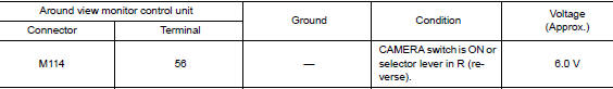
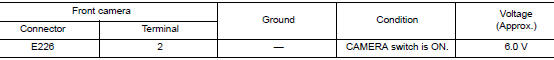
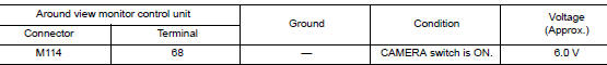
2.CHECK FRONT CAMERA POWER SUPPLY VOLTAGE
- Connect around view monitor control unit and front camera connectors.
- Turn ignition switch ON.
- Check voltage between around view monitor control unit connector M114 and ground.
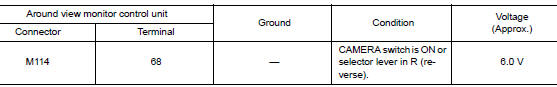
Is the inspection result normal? YES >> GO TO 3.
NO >> Replace around view monitor control unit. Refer to DAS-163, "Removal and Installation".
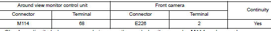
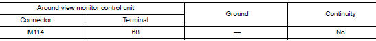
3.CHECK FRONT CAMERA IMAGE SIGNAL AND IMAGE SIGNAL GROUND CIRCUIT CONTINUITY
- Turn ignition switch OFF.
- Disconnect around view monitor control unit and front camera connectors.
- Check continuity between around view monitor control unit connector M114 and front camera connector E226.
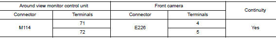
- Check continuity between around view monitor control unit connector M114 and ground.
Is the inspection result normal? YES >> GO TO 4.
NO >> Repair or replace harness or connectors.
4.CHECK FRONT CAMERA IMAGE SIGNAL
- Connect around view monitor control unit and front camera connectors.
- Turn ignition switch ON.
- Check signal between the terminals of around view monitor control unit connector M114.
Is the inspection result normal? YES >> Replace around view monitor control unit. Refer to DAS-163, "Removal and Installation".
NO >> Replace front camera. Refer to DAS-159, "Removal and Installation".
U111D SIDE CAMERA LH IMAGE SIGNAL CIRCUIT
DTC Logic
DTC DETECTION LOGIC
|
CONSULT Display |
DTC Detection Condition |
Possible Cause |
| Left side display output signal diagnosis (Harness disconnection) [U111D] | Left side camera image signal circuit open or short. | Check left side camera image signal circuit. |
Diagnosis Procedure
Regarding Wiring Diagram information, refer to DAS-53, "Wiring Diagram".
1.CHECK LH SIDE CAMERA POWER SUPPLY AND GROUND CIRCUIT CONTINUITY
- Turn ignition switch OFF.
- Disconnect around view monitor control unit and LH side camera connectors.
- Check continuity between around view monitor control unit connector M114 and LH side camera connector D4.
- Check continuity between around view monitor control unit connector M114 and ground.
Is the inspection result normal? YES >> GO TO 2.
NO >> Repair or replace harness or connectors.
2.CHECK LH SIDE CAMERA POWER SUPPLY VOLTAGE
- Connect around view monitor control unit and LH side camera connectors.
- Turn ignition switch ON.
- Check voltage between around view monitor control unit connector M114 and ground.
Is the inspection result normal? YES >> GO TO 3.
NO >> Replace around view monitor control unit. Refer to DAS-163, "Removal and Installation".
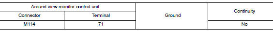
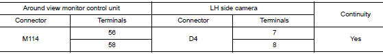
3.CHECK LH SIDE CAMERA IMAGE SIGNAL AND IMAGE SIGNAL GROUND CIRCUIT CONTINUITY
- Turn ignition switch OFF.
- Disconnect around view monitor control unit and LH side camera connectors.
- Check continuity between around view monitor control unit connector M114 and LH side camera connector D4.
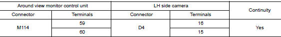
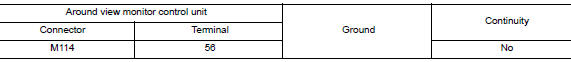
- Check continuity between around view monitor control unit connector M114 and ground.
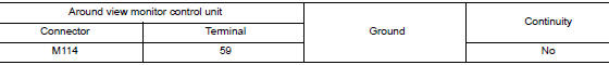
Is the inspection result normal? YES >> GO TO 4.
NO >> Repair or replace harness or connectors.
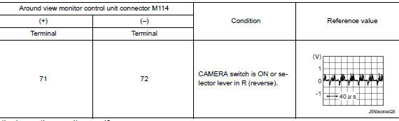
4.CHECK LH SIDE CAMERA IMAGE SIGNAL
- Connect around view monitor control unit and LH side camera connectors.
- Turn ignition switch ON.
- Check signal between the terminals of around view monitor control unit connector M114.
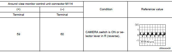
Is the inspection result normal? YES >> Replace around view monitor control unit. Refer to DAS-163, "Removal and Installation".
NO >> Replace LH side camera. Refer to DAS-161, "Removal and Installation".
U1232 STEERING ANGLE SENSOR
DTC Logic
DTC DETECTION LOGIC
|
CONSULT Display |
DTC Detection Condition |
Possible Cause |
| ST ANG SEN CALIB [U1232] | Predictive course line center position adjustment of steering angle sensor is incomplete. | Adjust predictive course line center position adjustment of steering angle sensor. |
Diagnosis Procedure
1.ADJUST PREDICTIVE COURSE LINE CENTER POSITION ADJUSTMENT OF STEERING ANGLE SENSOR
When U1232 is detected, the predictive course line center position of steering angle sensor needs to be adjusted.
>> Adjust the predictive course line center position of steering angle sensor. Refer to AV-291, "PREDICTED COURSE LINE CENTER POSITION ADJUSTMENT : Work Procedure".
U1302 CAMERA POWER VOLT
DTC Logic
DTC DETECTION LOGIC
|
CONSULT Display |
DTC Detection Condition |
Possible Cause |
| Camera supply power supply voltage abnormality [U1302] | Short in camera power supply circuit. |
|
Diagnosis Procedure
Regarding Wiring Diagram information, refer to DAS-53, "Wiring Diagram".
1.CHECK AVM CAMERA DATA MONITOR ITEMS
Check тАЬF-CAMERA IMAGE SIGNALтАЭ, тАЬREAR CAMERA IMAGE SIGNALтАЭ, тАЬDR-SIDE CAMERA IMAGE SIGтАЭ and тАЬPA-SIDE CAMERA IMAGE SIGтАЭ in тАЬDATA MONITORтАЭ of тАЬAVMтАЭ using CONSULT.
Is тАЬOKтАЭ displayed for all cameras? YES >> Refer to GI-41, "Intermittent Incident".
NO-1 (Front camera)>>GO TO 2.
NO-2 (Rear camera)>>GO TO 5.
NO-3 (LH side camera)>>GO TO 8.
NO-4 (RH side camera)>>GO TO 11.
2.CHECK FRONT CAMERA POWER SUPPLY (CAMERA)
- Turn ignition switch ON.
- Check voltage between front camera connector E226 and ground.
Is the inspection result normal? YES >> Replace front camera. Refer to DAS-159, "Removal and Installation".
NO >> GO TO 3.
3.CHECK FRONT CAMERA POWER SUPPLY (AROUND VIEW MONITOR CONTROL UNIT)
Check voltage between around view monitor control unit connector M114 and ground.
Is the inspection result normal? YES >> GO TO 4.
NO >> Replace around view monitor control unit. Refer to DAS-163, "Removal and Installation".
4.CHECK FRONT CAMERA POWER SUPPLY CIRCUIT CONTINUITY
- Turn ignition switch OFF.
- Disconnect around view monitor control unit connector M114 and front camera connector.
- Check continuity between around view monitor control unit connector M114 and front camera connector E226.
- Check continuity between around view monitor control unit connector M114 and ground.
Is the inspection result normal? YES >> Replace front camera. Refer to DAS-159, "Removal and Installation".
NO >> Repair or replace harness or connectors.
5.CHECK REAR CAMERA POWER SUPPLY (CAMERA)
- Turn ignition switch ON.
- Check voltage between rear camera connector D514 and ground.
Is the inspection result normal? YES >> Replace rear camera. Refer to DAS-166, "Removal and Installation".
NO >> GO TO 6.
6.CHECK REAR CAMERA POWER SUPPLY (AROUND VIEW MONITOR CONTROL UNIT)
Check voltage between around view monitor control unit connector M114 and ground.
Is the inspection result normal? YES >> GO TO 7.
NO >> Replace around view monitor control unit. Refer to DAS-163, "Removal and Installation".
7.CHECK REAR CAMERA POWER SUPPLY CIRCUIT CONTINUITY
- Turn ignition switch OFF.
- Disconnect around view monitor control unit connector M114 and rear camera connector.
- Check continuity between around view monitor control unit connector M114 and rear camera connector D514.
- Check continuity between around view monitor control unit connector M114 and ground.
Is the inspection result normal? YES >> Replace rear camera. Refer to DAS-166, "Removal and Installation".
NO >> Repair or replace harness or connectors.
8.CHECK SIDE CAMERA LH POWER SUPPLY (CAMERA)
- Turn ignition switch ON.
- Check voltage between side camera LH connector D14 and ground.
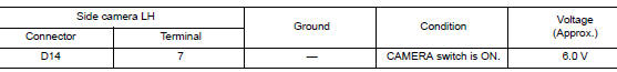
Is the inspection result normal? YES >> Replace side camera LH. Refer to DAS-161, "Removal and Installation".
NO >> GO TO 9.
9.CHECK SIDE CAMERA LH POWER SUPPLY (AROUND VIEW MONITOR CONTROL UNIT)
Check voltage between around view monitor control unit connector M114 and ground.
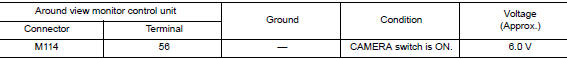
Is the inspection result normal? YES >> GO TO 10.
NO >> Replace around view monitor control unit. Refer to DAS-163, "Removal and Installation".
10.CHECK SIDE CAMERA LH POWER SUPPLY CIRCUIT CONTINUITY
- Turn ignition switch OFF.
- Disconnect around view monitor control unit connector M114 and side camera LH connector.
- Check continuity between around view monitor control unit connector M114 and side camera LH connector D14.
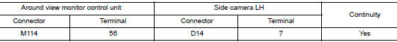
- Check continuity between around view monitor control unit connector M114 and ground.
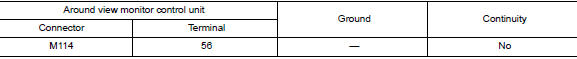
Is the inspection result normal? YES >> Replace side camera LH. Refer to DAS-161, "Removal and Installation".
NO >> Repair or replace harness or connectors.
11.CHECK SIDE CAMERA RH POWER SUPPLY (CAMERA)
- Turn ignition switch ON.
- Check voltage between side camera RH connector D107 and ground.
Is the inspection result normal? YES >> Replace side camera RH. Refer to DAS-161, "Removal and Installation".
NO >> GO TO 12.
12.CHECK SIDE CAMERA RH POWER SUPPLY (AROUND VIEW MONITOR CONTROL UNIT)
Check voltage between around view monitor control unit connector M114 and ground.
Is the inspection result normal? YES >> GO TO 13.
NO >> Replace around view monitor control unit. Refer to DAS-163, "Removal and Installation".
13.CHECK SIDE CAMERA RH POWER SUPPLY CIRCUIT CONTINUITY
- Turn ignition switch OFF.
- Disconnect around view monitor control unit connector M114 and side camera RH connector.
- Check continuity between around view monitor control unit connector M114 and side camera RH connector D107.
- Check continuity between around view monitor control unit connector M114 and ground.
Is the inspection result normal? YES >> Replace side camera RH. Refer to DAS-161, "Removal and Installation".
NO >> Repair or replace harness or connectors.
U1303 LED POWER SUPPLY VOLT
DTC Logic
DTC DETECTION LOGIC
|
CONSULT Display |
DTC Detection Condition |
Possible Cause |
| LED supply power supply voltage abnormality [U1303] | Open or short in blind spot warning indicator power supply circuit. |
|
Diagnosis Procedure
Regarding Wiring Diagram information, refer to DAS-53, "Wiring Diagram".
1.CHECK BLIND SPOT WARNING POWER SUPPLY CIRCUIT CONTINUITY
- Turn ignition switch OFF.
- Disconnect around view monitor control unit connector M113 and blind spot warning indicators connectors.
- Check continuity between around view monitor control unit connector M113 and blind spot warning indicators connectors.
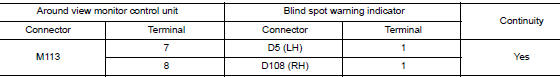
- Check continuity between around view monitor control unit connector M113 and ground.
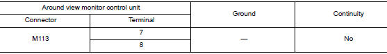
Is the inspection result normal? YES >> Replace around view monitor control unit. Refer to DAS-163, "Removal and Installation".
NO >> Repair or replace harness or connectors.
U1304 CAMERA IMAGE CALIBRATION
DTC Logic
DTC DETECTION LOGIC
|
CONSULT Display |
DTC Detection Condition |
Possible Cause |
| Non-completion of the calibration [U1304] | Camera image calibration is incomplete. | Perform calibration of camera image. |
Diagnosis Procedure
1.PERFORM CALIBRATION
When U1304 is detected, perform calibration of camera image.
>> Refer to AV-292, "CALIBRATING CAMERA IMAGE (AROUND VIEW MONITOR) : Work Procedure".
U1305 CONFIG UNFINISH
DTC Logic
DTC DETECTION LOGIC
|
CONSULT Display |
DTC Detection Condition |
Possible Cause |
| Non-completion of the configuration [U1305] | Configuration of around view monitor control unit is incomplete. | Perform configuration of around view monitor control unit. |
Diagnosis Procedure
1.PERFORM CONFIGURATION
When U1305 is detected, perform configuration of around view monitor control unit.
>> Refer to AV-290, "CONFIGURATION (AROUND VIEW MONITOR CONTROL UNIT) : Work Procedure".
U1308 CAMERA CONFIG
DTC Logic
DTC DETECTION LOGIC
|
CONSULT Display |
DTC Detection Condition |
Possible Cause |
| Rear camera judgement [U1308] | Around view monitor control unit camera calibration is incomplete. | Perform Around view monitor control unit camera calibration. |
Diagnosis Procedure
1.PERFORM AROUND VIEW MONITOR CAMERA CALIBRATION
When U1308 is detected, the rear view camera needs to be calibrated.
>> Calibrate the rear view camera. Refer to DAS-89, "Description".
U1309 PUMP UNIT CURRENT
DTC Logic
DTC DETECTION LOGIC
|
CONSULT Display |
DTC Detection Condition |
Possible Cause |
| PUMP UNIT CURRENT [U1309] | Around view monitor control unit detects incorrect pump current from rear view camera washer control unit. |
|
DTC CONFIRMATION PROCEDURE
1.PERFORM SELF DIAGNOSTIC RESULT
- Turn ignition switch ON.
- Perform тАЬSelf Diagnostic ResultтАЭ of тАЬAVMтАЭ using CONSULT.
Is DTC detected? YES >> Refer to DAS-125, "Diagnosis Procedure".
NO >> Inspection End.
Diagnosis Procedure
Regarding Wiring Diagram information, refer to DAS-53, "Wiring Diagram".
1.CHECK REAR VIEW CAMERA WASHER CONTROL UNIT POWER SUPPLY CIRCUIT
- Turn ignition switch ON.
- Check voltage between rear view camera washer control unit connector B67 and ground.
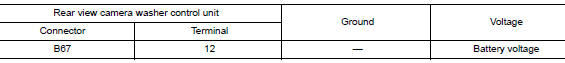
Is inspection result normal? YES >> GO TO 2.
NO >> Repair or replace harness or connectors.
2.CHECK REAR VIEW CAMERA WASHER CONTROL UNIT GROUND CIRCUIT
- Turn ignition switch OFF.
- Disconnect rear view camera washer control unit connector.
- Check continuity between rear view camera washer control unit connector B67 and ground.
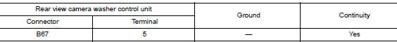
Is the inspection result normal? YES >> GO TO 3.
NO >> Repair or replace harness or connectors.
3.CHECK REAR VIEW CAMERA WASHER CONTROL UNIT CIRCUITS CONTINUITY
- Disconnect around view monitor control unit connector M113.
- Check continuity between around view monitor control unit connector M113 and rear view camera washer control unit connector B67
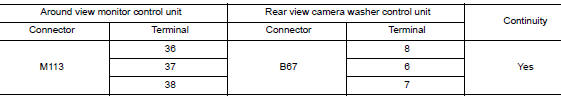
- Check continuity between around view monitor control unit connector M113 and ground.
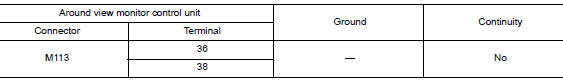
Is inspection result normal? YES >> GO TO 4.
NO >> Repair or replace harness or connectors.
4.CHECK CONTINUITY REAR VIEW CAMERA WASHER CONTROL UNIT TO PUMP
- Disconnect rear view camera air pump motor connector.
- Check continuity between rear view camera washer control unit connector B67 and rear view camera air pump motor connector B72.
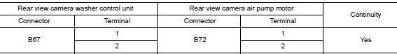
- Check for continuity between rear view camera washer control unit connector and ground.
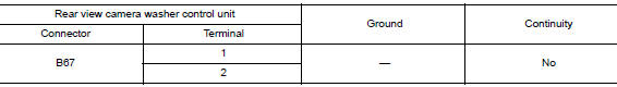
Is inspection result normal? YES >> Replace the rear view camera air pump motor. Refer to DAS-168, "Removal and Installation".
NO >> Repair or replace harness or connectors.
U130A PUMP CONTROL UNIT
DTC Logic
DTC DETECTION LOGIC
|
CONSULT Display |
DTC Detection Condition |
Possible Cause |
| PUMP ECU JUDGE [U130A] | Rear view camera washer control unit malfunction. | Rear view camera washer control unit. |
DTC CONFIRMATION PROCEDURE
1.PERFORM SELF DIAGNOSTIC RESULT
- Start the engine.
- Perform тАЬSelf Diagnostic ResultтАЭ of тАЬAVMтАЭ using CONSULT.
Is DTC detected? YES >> Refer to DAS-127, "Diagnosis Procedure".
NO >> Inspection End.
Diagnosis Procedure
1.CHECK REAR VIEW CAMERA WASHER CONTROL UNIT POWER SUPPLY CIRCUIT
- Turn ignition switch ON.
- Check voltage between rear view camera washer control unit connector B67 and ground.
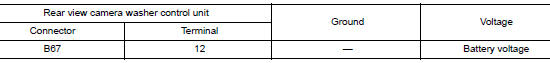
Is inspection result normal? YES >> GO TO 2.
NO >> Repair or replace harness or connectors.
2.CHECK REAR VIEW CAMERA WASHER CONTROL UNIT GROUND CIRCUIT
- Turn ignition switch OFF.
- Disconnect rear view camera washer control unit connector.
- Check continuity between rear view camera washer control unit connector B67 and ground.
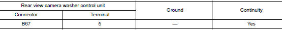
Is the inspection result normal? YES >> Replace rear view camera washer control unit. Refer to DAS-169, "Removal and Installation".
NO >> Repair or replace harness or connectors.
U130B REAR CAMERA COMM ERROR
DTC Logic
DTC DETECTION LOGIC
|
CONSULT Display |
DTC Detection Condition |
Possible Cause |
| Rear Camera Serial Communication [U130B] | Around view monitor control unit receives incorrect communication signal from rear view camera. |
|
DTC CONFIRMATION PROCEDURE
1.PERFORM SELF DIAGNOSTIC RESULT
- Turn ignition switch ON.
- Perform тАЬSelf Diagnostic ResultтАЭ of тАЬAVMтАЭ using CONSULT.
Is DTC detected? YES >> Refer to DAS-128, "Diagnosis Procedure".
NO >> Inspection End.
Diagnosis Procedure
Regarding Wiring Diagram information, refer to DAS-53, "Wiring Diagram".
1.CHECK REAR VIEW CAMERA SERIAL SIGNAL CIRCUIT CONTINUITY
- Turn ignition switch OFF.
- Disconnect around view monitor control unit connector M114 and rear camera connector.
- Check continuity between around view monitor control unit connector M114 and rear camera connector D514.
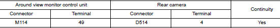
- Check continuity between around view monitor control unit connector M114 and ground.
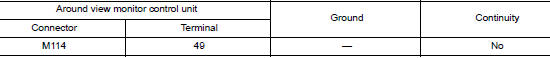
Is the inspection result normal? YES >> Replace around view monitor control unit. Refer to DAS-163, "Removal and Installation".
NO >> Repair or replace harness or connectors.
C10B7 YAW RATE SENSOR
DTC Logic
DTC DETECTION LOGIC
|
CONSULT Display |
DTC Detection Condition |
Possible Cause |
| YAW RATE SENSOR [C10B7] | Yaw rate/side/decel G sensor calibration incorrect. |
|
DTC CONFIRMATION PROCEDURE
1.PERFORM SELF DIAGNOSTIC RESULT
- Start the engine.
- Perform тАЬSelf Diagnostic ResultтАЭ of тАЬLASER/RADARтАЭ using CONSULT.
Is DTC detected? YES >> Refer to DAS-129, "Diagnosis Procedure".
NO >> Inspection End.
Diagnosis Procedure
1.PERFORM YAW RATE/SIDE/DECEL G SENSOR CALIBRATION
- Perform calibration of yaw rate/side/decel G sensor. Refer to BRC-72, "Work Procedure".
- Erase DTCs using CONSULT.
- Perform тАЬSelf Diagnostic ResultтАЭ of тАЬLASER/RADARтАЭ using CONSULT.
Is DTC detected? YES >> Replace the distance sensor. Refer to DAS-160, "Removal and Installation".
NO >> Inspection End.
C1A01 POWER SUPPLY CIRCUIT 1, C1A02 POWER SUPPLY CIRCUIT 2
DTC Logic
DTC DETECTION LOGIC
|
CONSULT Display |
DTC Detection Condition |
Possible Cause |
| POWER SUPPLY CIR [C1A01] | Distance sensor battery voltage is less than 7.9 V for 5 seconds. |
|
| POWER SUPPLY CIR 2 [C1A02] | Distance sensor battery voltage is greater than 19.3 V for 5 seconds. |
DTC CONFIRMATION PROCEDURE
1.PERFORM DTC CONFIRMATION PROCEDURE
- Start the engine.
- Perform тАЬSelf Diagnostic ResultтАЭ of тАЬLASER/RADARтАЭ using CONSULT.
Is DTC detected? YES >> Refer to DAS-130, "Diagnosis Procedure".
NO >> Refer to GI-41, "Intermittent Incident".
Diagnosis Procedure
1.CHECK DISTANCE SENSOR POWER SUPPLY AND GROUND CIRCUIT
Check power supply and ground circuit of distance sensor. Refer to DAS-144, "DISTANCE SENSOR : Diagnosis Procedure".
Is the inspection result normal? YES >> Replace the distance sensor. Refer to DAS-160, "Removal and Installation".
NO >> Repair or replace harness or connectors.
C1A03 VEHICLE SPEED SENSOR
AROUND VIEW MONITOR CONTROL UNIT
AROUND VIEW MONITOR CONTROL UNIT : DTC Logic
DTC DETECTION LOGIC
|
CONSULT Display |
DTC Detection Condition |
Possible Cause |
| VHCL SPEED SE CIRC [C1A03] | Around view monitor control unit detects a velocity calculation error. |
|
DTC CONFIRMATION PROCEDURE
1.PERFORM SELF DIAGNOSTIC RESULT
- Turn ignition ON.
- Perform тАЬSelf Diagnostic ResultтАЭ of тАЬAVMтАЭ using CONSULT.
Is DTC detected? YES >> Refer to DAS-131, "AROUND VIEW MONITOR CONTROL UNIT : Diagnosis Procedure".
NO >> Refer to GI-41, "Intermittent Incident".
AROUND VIEW MONITOR CONTROL UNIT : Diagnosis Procedure
1.CHECK ABS ACTUATOR AND ELECTRIC UNIT (CONTROL UNIT) SELF DIAGNOSTIC RESULT
Perform тАЬSelf Diagnostic ResultтАЭ of тАЬABSтАЭ using CONSULT.
Are any DTCs detected? YES >> Refer to BRC-55, "DTC Index".
NO >> Replace around view monitor control unit. Refer to DAS-163, "Removal and Installation".
DISTANCE SENSOR
DISTANCE SENSOR : DTC Logic
DTC DETECTION LOGIC
|
CONSULT Display |
DTC Detection Condition |
Possible Cause |
| VHCL SPEED SE CIRC [C1A03] | Distance sensor detects a velocity calculation error. |
|
DTC CONFIRMATION PROCEDURE
1.PERFORM SELF DIAGNOSTIC RESULT
- Turn ignition ON.
- Perform тАЬSelf Diagnostic ResultтАЭ of тАЬLASER/RADARтАЭ using CONSULT
Is DTC detected? YES >> Refer to DAS-131, "DISTANCE SENSOR : Diagnosis Procedure".
NO >> Refer to GI-41, "Intermittent Incident".
DISTANCE SENSOR : Diagnosis Procedure
1.CHECK ABS ACTUATOR AND ELECTRIC UNIT (CONTROL UNIT) SELF DIAGNOSTIC RESULT
Perform тАЬSelf Diagnostic ResultтАЭ of тАЬABSтАЭ using CONSULT.
Are any DTCs detected? YES >> Refer to BRC-55, "DTC Index".
NO >> Replace distance sensor. Refer to DAS-160, "Removal and Installation".
C1A04 ABS/TCS/VDC SYSTEM
AROUND VIEW MONITOR CONTROL UNIT
AROUND VIEW MONITOR CONTROL UNIT : DTC Logic
DTC DETECTION LOGIC
|
CONSULT Display |
DTC Detection Condition |
Possible Cause |
| ABS/TCS/VDC CIRC [C1A04] | Around view monitor control unit receives VDC failed message from ABS actuator and electric unit (control unit). |
|
DTC CONFIRMATION PROCEDURE
1.PERFORM SELF DIAGNOSTIC RESULT
- Turn ignition ON.
- Perform тАЬSelf Diagnostic ResultтАЭ of тАЬAVMтАЭ using CONSULT.
Is DTC detected? YES >> Refer to DAS-132, "AROUND VIEW MONITOR CONTROL UNIT : Diagnosis Procedure".
NO >> Inspection End.
AROUND VIEW MONITOR CONTROL UNIT : Diagnosis Procedure
1.CHECK ABS ACTUATOR AND ELECTRIC UNIT (CONTROL UNIT) SELF DIAGNOSTIC RESULT
Perform тАЬSelf Diagnostic ResultтАЭ of тАЬABSтАЭ using CONSULT.
Are any DTCs detected? YES >> Refer to BRC-55, "DTC Index".
NO >> Replace around view monitor control unit. Refer to DAS-163, "Removal and Installation".
DISTANCE SENSOR
DISTANCE SENSOR : DTC Logic
DTC DETECTION LOGIC
|
CONSULT Display |
DTC Detection Condition |
Possible Cause |
| ABS/TCS/VDC CIRC [C1A04] | Distance sensor receives VDC failed message from ABS actuator and electric unit (control unit). |
|
DTC CONFIRMATION PROCEDURE
1.PERFORM SELF DIAGNOSTIC RESULT
- Turn ignition ON.
- Perform тАЬSelf Diagnostic ResultтАЭ of тАЬLASER/RADARтАЭ using CONSULT.
Is DTC detected? YES >> Refer to DAS-132, "DISTANCE SENSOR : Diagnosis Procedure".
NO >> Inspection End.
DISTANCE SENSOR : Diagnosis Procedure
1.CHECK ABS ACTUATOR AND ELECTRIC UNIT (CONTROL UNIT) SELF DIAGNOSTIC RESULT
Perform тАЬSelf Diagnostic ResultтАЭ of тАЬABSтАЭ using CONSULT.
Are any DTCs detected? YES >> Refer to BRC-55, "DTC Index".
NO >> Replace distance sensor. Refer to DAS-160, "Removal and Installation".
C1A05 BRAKE SW/STOP LAMP SW
DTC Logic
DTC DETECTION LOGIC
NOTE: If DTC C1A05 is displayed with DTC U1000, first perform the trouble diagnosis for DTC U1000. Refer to DAS- 106, "DISTANCE SENSOR : DTC Logic".
|
CONSULT Display |
DTC Detection Condition |
Possible Cause |
| BRAKE SW/STOP L SW [C1A05] | Mismatch between stop lamp switch signal and ICC brake switch signal received from ECM and stop lamp switch signal received from ABS actuator and electric unit (control unit) that continues for 10 seconds or more with vehicle speeds at approximately 40 km/h or more. |
|
Diagnosis Procedure
1.CHECK SELF DIAGNOSTIC RESULT OF ECM
- Perform тАЬSelf Diagnostic ResultтАЭ of тАЬENGINEтАЭ using CONSULT.
Are any DTCs detected? YES >> Refer to EC-93, "DTC Index".
NO >> GO TO 2.
2.CHECK SELF DIAGNOSTIC RESULT OF ABS
- Perform тАЬSelf Diagnostic ResultтАЭ of тАЬABSтАЭ using CONSULT.
Are any DTCs detected? YES >> Refer to BRC-55, "DTC Index".
NO >> Replace distance sensor. Refer to DAS-160, "Removal and Installation".
C1A12 LASER BEAM OFF CENTER
DTC Logic
DTC DETECTION LOGIC
|
CONSULT Display |
DTC Detection Condition |
Possible Cause |
| LASER BEAM OFFCNTR [C1A12] | Distance sensor is off the aiming point. | Distance sensor. |
Diagnosis Procedure
1.PERFORM DISTANCE SENSOR SELF DIAGNOSTIC RESULT
Perform тАЬSelf Diagnostic ResultтАЭ of тАЬLASER/RADARтАЭ using CONSULT.
Is DTC detected? YES >> Replace distance sensor. Refer to DAS-160, "Removal and Installation".
NO >> Inspection End.
C1A14 ECM
DTC Logic
DTC DETECTION LOGIC
NOTE: If DTC C1A14 is displayed with DTC U1000, first perform the trouble diagnosis for DTC U1000. Refer to DAS- 106, "DISTANCE SENSOR : DTC Logic".
|
CONSULT Display |
DTC Detection Condition |
Possible Cause |
| ECM CIRCUIT [C1A14] | ECM is malfunctioning. |
|
1.PERFORM SELF DIAGNOSTIC RESULT
- Sta
DIAGNOSIS AND REPAIR WORK FLOW Work Flow OVERALL SEQUENCE DETAILED FLOW 1.INTERVIEW FOR MALFUNCTION It is also important to clarify the customer concerns before starting the inspection. Int ... Basic inspection
DRIVER ASSISTANCE SYSTEM SYMPTOMS Symptom Table LANE DEPARTURE WARNING SYSTEM SYMPTOMS NOTE: Refer to the following the operation condition of the Lane Departure Warning system. Lane D ... Symptom diagnosis
Other materials:
Wiring diagram
Wiring Diagram ...Symptom diagnosis
EXTERIOR LIGHTING SYSTEM SYMPTOMS Symptom Table CAUTION: Perform the self-diagnosis with CONSULT before the symptom diagnosis. Perform the trouble diagnosis if any DTC is detected. NORMAL OPERATING CONDITION Description AUTO LIGHT SYSTEM The headlamp may not be turned ON/OFF immedi ...Brake booster
Exploded View Spacer Gasket Brake booster Check valve Reservoir tank Brake fluid level sensor Brake booster pressure sensor Removal and installation REMOVAL Remove the cowl top. Refer to EXT-25, "Removal and Installation". Remove th ...┬й 2014-2025 Copyright www.nirogue.com