Nissan Rogue Service Manual: Brake booster
Exploded View
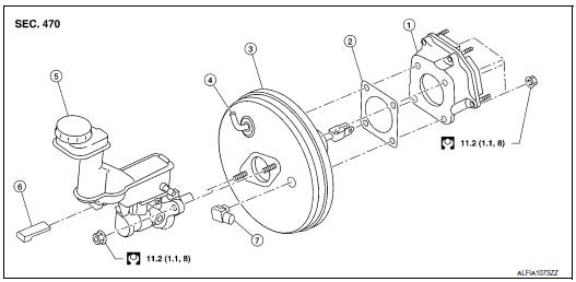
- Spacer
- Gasket
- Brake booster
- Check valve
- Reservoir tank
- Brake fluid level sensor
- Brake booster pressure sensor
Removal and installation
REMOVAL
- Remove the cowl top. Refer to EXT-25, "Removal and Installation".
- Remove the instrument lower panel LH. Refer to IP-22, "Removal and Installation".
- Remove the knee protector. Refer to IP-14, "Exploded View".
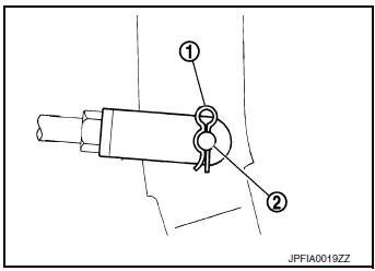
- Remove the snap pin (1) and clevis pin (2) from the brake pedal.
- Disconnect vacuum hose from brake booster. Refer to BR-32, "Exploded View".
- Remove master cylinder assembly. Refer to BR-27, "Removal and Installation".
- Disconnect the harness connector from the brake booster pressure sensor.
- Remove the brake booster pressure sensor.
- Remove the nuts on the brake booster and brake pedal.
CAUTION: Secure the brake booster to avoid damage to components.
- Remove the brake booster.
CAUTION: Do not deform or bend the brake pipes.
INSTALLATION
- Install a new gasket between the brake booster and dash panel.
CAUTION: Do not reuse the gasket.
- Install the brake booster to the dash panel from the engine room
side.
CAUTION: Do not damage brake booster stud bolt threads during installation.
- Install the nuts to the brake booster and brake pedal. Refer to BR-30, "Exploded View".
- Install the brake booster pressure sensor.
- Connect the harness connector to the brake booster pressure sensor.
- Install master cylinder assembly. Refer to BR-27, "Removal and Installation".
- Connect vacuum hose to brake booster. Refer toBR-32, "Exploded View".
- Install the clevis pin and snap pin to the brake pedal.
- Adjust the brake pedal. Refer to BR-15, "Adjustment".
- Install the knee protector. Refer to IP-14, "Exploded View".
- Install instrument lower panel LH. Refer to IP-22, "Removal and Installation".
- Bleed the brake system. Refer to BR-16, "Bleeding Brake System".
- Inspect the brake booster. Refer to BR-10, "Inspection".
 Brake master cylinder
Exploded View
Reservoir cap
Oil strainer
Reservoir tank
Brake fluid level sensor
Cylinder body
Pin
O-ring
Grommet
: Apply PBC (Poly Butyl
Cuprysil) grease or sil ...
 Vacuum lines
Exploded View
Clamp
Vacuum hose
Vacuum tube
Clip
Vacuum hose
To intake manifold
To brake booster
Paint mark
Stamp indicating engine direction
Removal an ...
Other materials:
Removal and installation
NATS ANTENNA AMP.
Removal and Installation
REMOVAL
Remove the steering column covers. Refer to IP-17, "Removal and
Installation".
Disconnect the harness connector from the NATS antenna amp.
Release pawls and remove NATS antenna amp. (1) from the
ignition sw ...
Power supply and ground circuit
BCM (BODY CONTROL SYSTEM) (WITH INTELLIGENT KEY SYSTEM)
BCM (BODY CONTROL SYSTEM) (WITH INTELLIGENT KEY SYSTEM) : Diagnosis
Procedure
Regarding Wiring Diagram information, refer to BCS-50, "Wiring Diagram".
1. CHECK FUSE
Check that the following fuse is not blown.
Is the fuse blo ...
P2122, P2123 APP sensor
DTC Description
DTC DETECTION LOGIC
DTC No.
CONSULT screen terms
(Trouble diagnosis content)
DTC detecting condition
P2122
APP SEN 1/CIRC
(Throttle/pedal position sensor/switch ″D″
circuit low)
An excessively low voltage from the APP sensor 1 is sen ...
