Nissan Rogue Service Manual: Component parts
Component Parts Location
- Instrument lower panel LH
|
No. |
Component |
Function |
| 1 | Combination meter |
Refer to MWI-6, "METER SYSTEM : Component Parts Location" for detailed installation location. |
| 2 | TCM |
Refer to TM-12, "CVT CONTROL SYSTEM : Component Parts Location" for detailed installation location. |
| 3 | ECM |
Refer to EC-14, "Component Parts Location" for detailed installation location. |
| 4 | SPORT mode switch | Refer to DMS-4, "SPORT Mode Switch". |
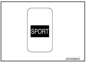
SPORT Mode Switch
- The SPORT mode switch is installed to the instrument lower finisher.
- When the SPORT mode indicator lamp on the combination meter is OFF and the SPORT mode switch is pressed, the SPORT mode is active and the SPORT mode indicator lamp is ON.
- When the SPORT mode indicator lamp on the combination meter is ON and the SPORT mode switch is pressed, the SPORT mode is cancelled and the SPORT mode indicator lamp is OFF.
SPORT Mode Indicator Lamp
DESIGN/PURPOSE
The SPORT mode indicator lamp inform the driver that the vehicle is in SPORT mode.

BULB CHECK
Not applicable
SYSTEM DIAGRAM
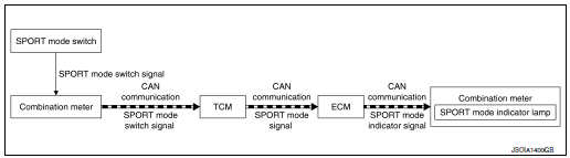
SIGNAL PATH
- TCM receives SPORT mode switch signal (ON/OFF) from combination
meter via CAN communication.
Based on the signal, TCM transmits SPORT mode signal to ECM via CAN communication.
- ECM transmits SPORT mode indicator signal to combination meter via CAN communication. Based on the signal, combination meter illuminates SPORT mode indicator lamp.
LIGHTING CONDITION
When all of the following conditions are satisfied
- Ignition switch: ON
- The SPORT mode switch is pressed when the SPORT mode indicator lamp is OFF
SHUTOFF CONDITION
When any of the condition listed below is satisfied.
- Ignition switch: Other than ON
- The SPORT mode switch is pressed when the SPORT mode indicator lamp is ON.

 System
SPORT MODE CONTROL
SPORT MODE CONTROL : System Description
SYSTEM DIAGRAM
SYSTEM DISCRIPTION
TCM receives SPORT mode switch signal (ON/OFF) from combination
meter via CAN communica ...
Other materials:
Structure and operation
Positive Crankcase Ventilation
This system returns blow-by gas to the intake manifold.
The positive crankcase ventilation (PCV) valve is provided to conduct crankcase
blow-by gas to the intake
manifold.
During partial throttle operation of the engine, the intake manifold sucks the
bl ...
VIN registration
Description
VIN Registration is an operation to registering VIN in ECM. It must be
performed each time ECM is replaced.
NOTE:
Accurate VIN which is registered in ECM may be required for Inspection &
Maintenance (I/M).
Work Procedure
1.CHECK VIN
Check the VIN of the vehicle and note it. ...
CVT oil warmer
Exploded View
Transaxle assembly
CVT oil warmer
: N·m (kg-m, in-lb)
Removal and Installation
REMOVAL
WARNING:
Do not remove the radiator cap when the engine is hot. Serious burns could occur
from high pressure
engine coolant escaping from the radiator. Wrap a thick cloth around ...
