Nissan Rogue Service Manual: Component parts
Component Parts Location
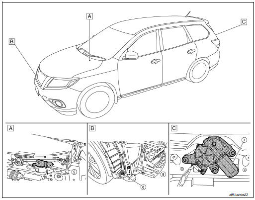
- View of cowl area (with cowl top cover removed)
- RH front of vehicle (with front bumper fascia removed)
- View with back door finisher removed
|
No. |
Component |
Function |
| 1 | Combination switch (Wiper and washer switch) | Refer to WW-8, "FRONT WIPER AND WASHER SYSTEM : System Description".
Refer to BCS-76, "Removal and Installation". |
| 2 | Combination meter | Transmits the vehicle speed signal to BCM via CAN communication. |
| 3 | IPDM E/R |
Refer to WW-6, "Component Parts Location" |
| 4 | BCM |
Refer to WW-6, "Component Parts Location". |
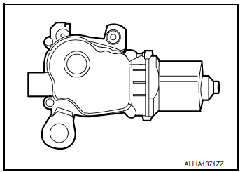
| 5 | Front wiper motor | Refer to WW-7, "Front wiper motor". |
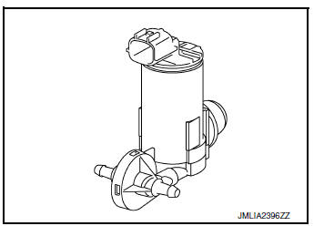
| 6 | Front and rear washer motor | Refer to WW-7, "Washer pump". |
| 7 | Rear wiper motor | Refer to WW-7, "Rear wiper motor". |
| 8 | Washer Fluid Level Switch | Transmits the washer fluid level switch signal to the combination meter. |
Front wiper motor
- Controls front wiper operation with IPDM E/R control.
- Transmits front wiper stop position signal to IPDM E/R.
Washer pump
- Washer fluid is sprayed according to washer switch states.
- Switching between front washer and rear washer is performed according to the voltage polarity change to washer pump.
Washer fluid level switch
Detects that washer fluid level is low and transmits washer fluid level switch signal to combination meter.
Rear wiper motor
- Controls rear wiper operation with BCM control.
- Transmits rear wiper stop position signal to BCM.

 System
FRONT WIPER AND WASHER SYSTEM
FRONT WIPER AND WASHER SYSTEM : System Diagram
FRONT WIPER AND WASHER SYSTEM : System Description
OUTLINE
FRONT WIPER CONTROL (BASIC)
BCM detects the co ...
Other materials:
Engine control system
Symptom Table
SYSTEM — BASIC ENGINE CONTROL SYSTEM
1 - 6: The numbers refer to the order of inspection.
(continued on next table)
SYSTEM — ENGINE MECHANICAL & OTHER
1 - 6: The numbers refer to the order of inspection. ...
Water hose
Exploded View
Water outlet
Hose clamp
Water hose A
Clip
CVT oil warmer
Transaxle assembly
Water hose B
Heater thermostat
Water hose C
: Always replace after every
disassembly.
: N·m (kg-m, ft-lb)
Removal and Installation
REMOVAL
WARNING:
Do not remove the rad ...
Removal and installation
FRONT COMBINATION LAMP
Exploded View
Front fender
Front combination lamp
Clip
Removal and Installation
REMOVAL
Remove front bumper fascia. Refer to EXT-17, "Removal and
Installation".
Remove front combination lamp bolts and clip.
Pull front c ...
