Nissan Rogue Service Manual: System
FRONT WIPER AND WASHER SYSTEM
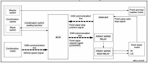
FRONT WIPER AND WASHER SYSTEM : System Diagram
FRONT WIPER AND WASHER SYSTEM : System Description
OUTLINE
FRONT WIPER CONTROL (BASIC)
- BCM detects the combination switch position by the combination switch reading function.
- BCM transmits the front wiper request signal to the IPDM E/R using CAN communication.
- IPDM E/R controls the integrated front wiper relay and front wiper high relay based on the status of the front wiper request signal.
- IPDM E/R provides power to operate the front wiper motor.
LOW SPEED OPERATION
- Ignition switch ON.
- Front wiper switch in LO or MIST position.
- BCM reads the combination switch position and transmits the front wiper request signal (LO) to IPDM E/R using CAN communication.
- IPDM E/R turns ON the front wiper relay.
HIGH SPEED OPERATION
- Ignition switch ON.
- Front wiper switch in HI.
- BCM reads the combination switch position and transmits the front wiper request signal (HI) to IPDM E/R using CAN communication.
- IPDM E/R turns ON the front wiper relay and the front wiper high relay.
INTERMITTENT OPERATION
- Ignition switch ON.
- Front wiper switch INT.
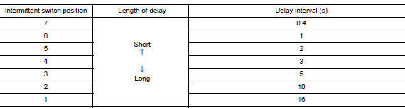
- BCM reads the combination switch position. BCM calculates the delay interval based on the table below and then transmits the front wiper request signal (INT) to IPDM E/R using CAN communication.
- IPDM E/R turns ON the front wiper relay only once.
- BCM detects stop position of the front wiper motor based on the front wiper stop position signal received from the IPDM E/R.
- BCM transmits the front wiper request signal (INT) again after the delay interval.
AUTO STOP OPERATION
- Front wiper switch is turned OFF.
- BCM monitors wiper switch position by combination switch reading position function.
- BCM stops transmitting the front wiper request signal to the IPDM E/R.
- IPDM E/R detects the front wiper auto stop signal from the position of the front wiper motor (stop position/ except stop position).
- When the front wiper request signal is stopped, IPDM E/R turns ON the front wiper relay until the front wiper motor returns to the stop position.
- IPDM E/R turns the front wiper relay OFF when the front wiper motor has reached the stop position.

MIST OPERATION
- Ignition switch ON.
- Front washer switch in OFF position.
- Front wiper switch in MIST position.
- BCM reads the combination switch position and transmits the front wiper request signal (LO) to IPDM E/R using CAN communication.
- IPDM E/R turns ON the front wiper relay.
- The front wiper operates once after the front washer operation.
WIPER/WASHER OPERATION
- Ignition switch ON.
- Front washer switch ON.
- The front washer switch provides ground for the front and rear washer motor.
- BCM reads the combination switch position and transmits the front wiper request signal (LO) to IPDM E/R using CAN communication.
- BCM transmits the front wiper request signal (LO) to IPDM E/R using CAN communication.
- IPDM E/R turns ON the front wiper relay.
- The front wiper operates.
NOTE: BCM transmits the front wiper request signal (LO) so that the front wiper operates approximately 3 times after front washer switch OFF is detected.
FRONT WIPER AND WASHER SYSTEM : Fail-Safe
FAIL−SAFE OPERATION
IPDM E/R performs the fail-safe function when the front wiper auto stop circuit is malfunctioning. Refer to WW- 10, "FRONT WIPER AND WASHER SYSTEM : Fail-Safe".
REAR WIPER AND WASHER SYSTEM
REAR WIPER AND WASHER SYSTEM : System Description
SYSTEM DIAGRAM
OUTLINE
The rear wiper is controlled by each function of BCM.
Control by BCM
- Combination switch reading function
- Rear wiper control function
REAR WIPER BASIC OPERATION
- BCM detects the combination switch condition by the combination switch reading function.
- BCM controls the rear wiper to start or stop.
REAR WIPER ON OPERATION
- BCM supplies power to the rear wiper motor according to the rear wiper ON operating condition.
Rear wiper ON operating condition
- Power switch ON
- Rear wiper switch ON
REAR WIPER INT OPERATION
- BCM supplies power to the rear wiper motor according to the INT operating condition.
Rear wiper INT operating condition
- Power switch ON
- Rear wiper switch INT
- BCM controls the rear wiper to operate once.
- BCM detects the rear wiper motor stopping position.
- BCM supplies power to the rear wiper motor after an intermittent from the stop of the rear wiper motor.
REAR WIPER AUTO STOP OPERATION
- BCM stops supplying power to the rear wiper motor when the rear wiper switch is turned OFF.
- BCM reads a rear wiper stop position signal from the rear wiper motor to detect a rear wiper motor position.
- When the rear wiper motor is at other than the stopping position, BCM continues to supply power to the rear wiper motor until it returns to the stopping position.
NOTE: BCM stops supplying power to the rear wiper motor when the power switch is turned OFF.
REAR WIPER OPERATION LINKED WITH WASHER
- BCM supplies power to the rear wiper motor according to the washer linked operating condition of rear wiper. When the rear washer switch is turned OFF, BCM controls rear wiper to operate approximately 3 times.
Washer linked operating condition of rear wiper
- Power switch ON
- Rear washer switch ON (0.4 second or more)
- The washer pump is grounded through the combination switch with the rear washer switch ON.
REAR WIPER AND WASHER SYSTEM : Fail-safe
FAIL−SAFE OPERATION
IPDM E/R performs the fail-safe function when the rear wiper auto stop circuit is malfunctioning. Refer to WW- 11, "REAR WIPER AND WASHER SYSTEM : Fail-safe".
 Component parts
Component Parts Location
View of cowl area (with cowl top cover
removed)
RH front of vehicle (with front
bumper fascia removed)
View with back door finisher removed
No.
...
 Diagnosis system (BCM) (with intelligent key system)
COMMON ITEM
COMMON ITEM : CONSULT Function (BCM - COMMON ITEM)
APPLICATION ITEM
CONSULT performs the following functions via CAN communication with BCM.
Direct Diagnostic Mode
De ...
Other materials:
Basic inspection
DIAGNOSIS AND REPAIR WORK FLOW
Work Flow
OVERALL SEQUENCE
DETAILED FLOW
1.INTERVIEW FOR MALFUNCTION
It is also important to clarify the customer concerns before starting the
inspection. Interview the customer
about the concerns carefully and understand the symptoms fully.
NOTE:
The cus ...
ECO mode switch (if so equipped)
ECO mode switch
The ECO mode helps to enhance the fuel
economy by controlling the throttle sensitivity and
transmission points.
To turn on the ECO mode, push the ECO mode
switch. The ECO mode indicator light (on the
speedometer) will remain lit while the mode is
active.
To turn off t ...
Warning/indicator lights and audible reminders
Anti-lock Braking System (ABS)
warning light
Brake warning light
Charge warning light
Low tire pressure warning light
Low windshield washer fluid warning light (if so
equipped)
Master warning light
Power s ...
