Nissan Rogue Service Manual: Center console assembly
Exploded View
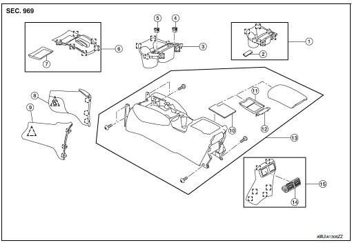
- Center console cup holder (without heated seats)
- Coin tray insert
- Center console cup holder (with heated seats)
- Front heated seat switch (RH)
- Front heated seat switch (LH)
- Shift selector finisher
- Shift selector finisher mat
- Center console side finisher (RH)
- Center console side finisher (LH)
- Center console tray
- Center console bin mat
- Center console rear brace finisher
- Center console assembly
- Rear center ventilator grille
- Center console rear finisher
 Metal clip
 Clip
Clip
 Pawl
Pawl
Removal and Installation
REMOVAL
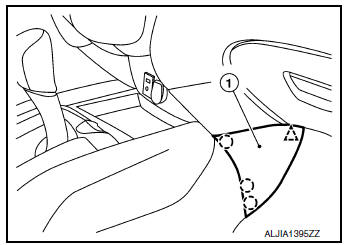
- Release clips and pawls using a suitable tool and remove center console side finisher (1) (LH/RH).
: Pawl
: Clip
NOTE: RH side shown; LH similar.
- Remove shift selector knob. Refer to TM-194, "Exploded View".
- Remove cluster lid C. Refer to IP-21, "Removal and Installation".
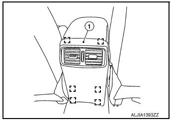
- Release clips using a suitable tool and remove center console
rear finisher (1).: Metal clip
- Remove center console screws (A).
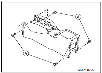
- Disconnect the harness connectors and remove center console.
INSTALLATION
Installation is in the reverse order of removal.
 Steering column covers
Removal and Installation
REMOVAL
Release gap hider (1) pawls from the steering column upper
cover (2).
: Pawl
Remove steering column cover screws (A)
NOTE:
Rotate steering w ...
 Cluster lid A
Removal and Installation
REMOVAL
Remove instrument lower panel LH. Refer to IP-22, "Removal and
Installation".
Remove instrument finisher A. Refer to IP-15, "INSTR ...
Other materials:
Tire chains
Use of tire chains may be prohibited according to
location. Check the local laws before installing
tire chains. When installing tire chains, make sure
they are the proper size for the tires on your
vehicle and are installed according to the chain
manufacturer’s suggestions. Use only SAE
clas ...
Washer level switch signal circuit
Description
Transmits the washer fluid level switch signal to the combination meter.
Diagnosis Procedure
Regarding Wiring Diagram information, refer to MWI-32, "Wiring Diagram".
1.CHECK WASHER FLUID LEVEL SWITCH SIGNAL CIRCUIT
Turn ignition switch OFF.
Disconnect comb ...
Preparation
Special Service Tool
The actual shape of the tools may differ from those illustrated here.
Tool number
(TechMate No.)
Tool name
Description
—
(J-43897-18)
Oxygen sensor thread cutter
Reconditioning the exhaust system threads
before installing ...
