Nissan Rogue Service Manual: Washer level switch signal circuit
Description
Transmits the washer fluid level switch signal to the combination meter.
Diagnosis Procedure
Regarding Wiring Diagram information, refer to MWI-32, "Wiring Diagram".
1.CHECK WASHER FLUID LEVEL SWITCH SIGNAL CIRCUIT
- Turn ignition switch OFF.
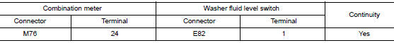
- Disconnect combination meter harness connector M76 and washer fluid level switch harness connector E82.
- Check continuity between combination meter harness connector M76 and washer fluid level switch harness connector E82.
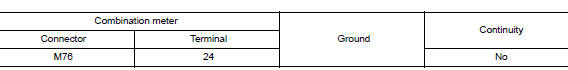
- Check continuity between combination meter harness connector and ground.
Is the inspection result normal? YES >> GO TO 2.
NO >> Repair or replace harness or connector.
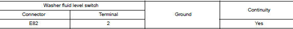
2.CHECK WASHER FLUID LEVEL SWITCH GROUND CIRCUIT
Check continuity between washer fluid level switch connector and ground.
Is the inspection result normal? YES >> Inspection End.
NO >> Repair or replace harness or connector.
Component Inspection
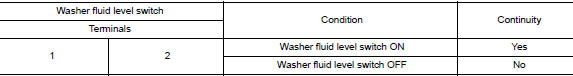
1.CHECK WASHER FLUID LEVEL SWITCH
- Turn ignition switch OFF.
- Disconnect washer fluid level switch connector.
- Check washer fluid level switch.
Is the inspection result normal?
YES >> Inspection End.
NO >> Replace washer fluid level switch. Refer to WW-58, "Removal and Installation".
 Steering switch
Description
When one of the steering switches is pushed, the resistance in the steering
switch changes the signal to
identify which button is controlling the information display.
Diagnosis Proced ...

Other materials:
P0863 TCM communication
DTC Description
DTC DETECTION LOGIC
DTC
CONSULT screen terms
(Trouble diagnosis content)
DTC detection condition
P0863
CONTROL UNIT (CAN)
(TCM Communication Circuit)
An error is detected at the initial CAN diagnosis of TCM.
POSSIBLE CAUSE
TCM
FAIL-SAFE
...
Remote keyless entry system (if so equipped)
WARNING
Radio waves could adversely affect
electric medical equipment. Those who
use a pacemaker should contact the
electric medical equipment manufacturer
for the possible influences before
use.
The remote keyless entry keyfob transmits
radio waves ...
Symptom diagnosis
POWER DOOR LOCK SYSTEM SYMPTOMS
Symptom Table
DOOR LOCK/UNLOCK FUNCTION MALFUNCTION
NOTE:
Before performing the diagnosis in the following table, check
ŌĆ£WORK FLOWŌĆØ. Refer to DLK-312, "Work
Flow".
Check that vehicle is under the condition shown in ŌĆ£Conditions ...
