Nissan Rogue Service Manual: Camshaft valve clearance
Camshaft valve clearance
- Perform this inspection as follows after removal, installation, or replacement of the camshaft or any valve parts, or if there are any unusual engine conditions due to changes in valve clearance over time (starting, idling, and/or noise).
- Remove the fender protector side cover (RH). Refer to EXT-28, "FENDER PROTECTOR : Exploded View".
- Remove the rocker cover. Refer to EM-37, "Exploded View".
- Turn crankshaft pulley clockwise when viewed from front to align TDC identification mark (B) with timing indicator (A).
NOTE: Do not confuse TDC mark (B) with paint marks (C).
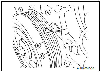
- At this time, check that the both intake and exhaust cam lobes of No. 1 cylinder face outside.
- If they do not face outside, turn crankshaft pulley once more.
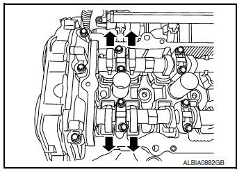
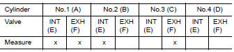
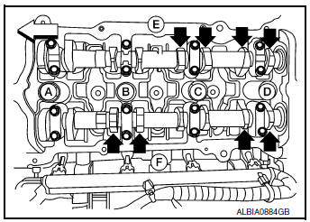
- Measure valve clearances with a suitable tool at locations marked (X) in the table below.
- No.1 cylinder compression TDC.
 Engine front
- Use a suitable tool to measure the clearance between valve lifter and camshaft.
Valve clearance: Refer to EM-116, "Camshaft".
- Turn crankshaft one complete revolution (360°) and align mark on crankshaft pulley with pointer.
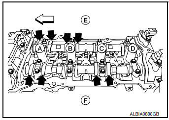
- Measure valve clearances with a suitable tool at locations marked (X) in the table below.
- No.4 cylinder compression TDC.
If out of specifications, make necessary adjustment.
 Engine front
ADJUSTMENT
NOTE:
- Perform adjustment by selecting the valve lifter with the correct head thickness.
- Remove camshaft. Refer to EM-64, "Exploded View".
- Remove the valve lifters at the locations that are outside the standard.
- Measure the center thickness of the removed valve lifters with a suitable tool (A).
- Use the equation below to calculate valve lifter thickness for replacement.
- Valve lifter thickness calculation.
t = t1 + (C1 - C2)
t = Thickness of replacement valve lifter.
t1 = Thickness of removed valve lifter.
C1 = Measured valve clearance.
C2 = Standard valve clearance.
- Thickness of a new valve lifter (B) can be identified by stamp
marks (A) on the reverse side (inside the cylinder).
Stamp mark 324H indicates a thickness of 3.24 mm (0.1276 in) Available thickness of valve lifter: 26 sizes with a range of 3.00 to 3.50 mm (0.1181 to 0.1378 in), in steps of 0.02 mm (0.0008 in), when assembled at the factory.
- Install the selected valve lifter.
- Install camshaft. Refer to EM-64, "Exploded View".
- Install timing chain and related parts. Refer to EM-44, "Exploded View".
- Manually rotate crankshaft pulley a few rotations.
- Check that valve clearances for cold engine are within specifications by referring to the specified values.
Valve clearance Refer to EM-116, "Camshaft".
- Install all removed parts in the reverse order of removal.
- Warm up the engine, and check for unusual noise and vibration.
 Spark plug
Exploded view
Ignition coil
Spark plug
Rocker cover
Removal and installation
REMOVAL
Remove air duct assembly.
Remove ignition coil. Refer to EM-36, "Ex ...
 Compression pressure
CHECKING COMPRESSION PRESSURE
Warm up the engine to full operating temperature.
Release the fuel pressure. Refer to EC-144, "Work Procedure".
Remove the ignition co ...
Other materials:
Corrosion protection
Most common factors contributing to vehicle
corrosion
Most vehicle corrosion is caused by:
the accumulation of moisture-retaining dirt
and debris in body panel sections, cavities,
and other areas
damage to paint and other protective coatings
caused by gravel and stone chip ...
Luggage room lamp
Removal and Installation
REMOVAL
Insert a suitable tool (A) into the gap between the luggage lower
finisher (RH) (2) and the top of luggage room lamp (1) to release
the pawl.
: Pawl
Disconnect the harness connector from the luggage room lamp and remove.
INSTALLATION
Installati ...
P0125 ECT sensor
DTC Description
DTC DETECTION LOGIC
DTC No.
CONSULT screen terms
(Trouble diagnosis content)
DTC detecting condition
P0125
ECT SENSOR
(Insufficient coolant temperature for closed
loop fuel control)
Voltage sent to ECM from the sensor is not practical, ...
