Nissan Rogue Service Manual: Basic inspection
DIAGNOSIS AND REPAIR WORK FLOW
Work Flow
OVERALL SEQUENCE
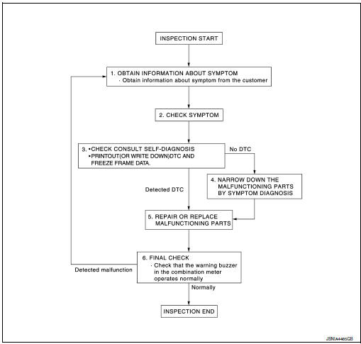
DETAILED FLOW
1.OBTAIN INFORMATION ABOUT SYMPTOM
Interview the customer to obtain as much information as possible about the conditions and environment under which the malfunction occurred.
>> GO TO 2.
2.CHECK SYMPTOM
- Check the symptom based on the information obtained from the customer.
- Check if any other malfunctions are present.
> GO TO 3.
3.CHECK CONSULT SELF-DIAGNOSIS RESULTS
- Connect CONSULT and perform "self-diagnosis". Refer to WCS-27, "DTC Index".
- When DTC is detected, follow the instructions below:
- Record DTC and Freeze Frame Data.
Are self-diagnosis results normal? YES >> GO TO 4.
NO >> GO TO 5.
4.NARROW DOWN MALFUNCTIONING PARTS BY SYMPTOM DIAGNOSIS
Perform symptom diagnosis and narrow down the malfunctioning parts.
>> GO TO 5.
5.REPAIR OR REPLACE MALFUNCTIONING PARTS
Repair or replace malfunctioning parts.
NOTE: If DTC is displayed, erase DTC after repairing or replacing malfunctioning parts.
>> GO TO 6.
6.FINAL CHECK
Check that the warning buzzer in the combination meter operates normally.
Does it operate normally? YES >> Inspection End.
NO >> GO TO 1.
 Wiring diagram
Wiring Diagram
...

Other materials:
Removal and installation
NATS ANTENNA AMP.
Removal and Installation
REMOVAL
Remove the steering column covers. Refer to IP-17, "Removal and
Installation".
Disconnect the harness connector from the NATS antenna amp.
Release pawls and remove NATS antenna amp. (1) from the
ignition sw ...
DTC/circuit diagnosis
U0428 STEERING ANGLE SENSOR
DTC Logic
DTC DETECTION LOGIC
CONSULT Display
DTC Detection Condition
Possible Cause
ST ANG SEN CALIB
[U0428]
Predictive course line center position adjustment
of steering angle sensor is incomplete.
Adjust predictive cours ...
Oil cooler
Exploded View
Intake manifold
Cylinder block
Clamp
Water hose
Water hose clip
Water hose
Oil cooler
Gasket
Oil cooler relief valve
Front
Removal and Installation
WARNING:
Be careful not to burn yourself, as engine oil and ...
