Nissan Rogue Service Manual: B terminal circuit
Description
“B” terminal circuit supplies power to charge the battery and to operate the vehicles electrical system.
Diagnosis Procedure
Regarding Wiring Diagram information. Refer to CHG-7, "Wiring Diagram".
1.CHECK “B” TERMINAL CONNECTION
- Turn ignition switch OFF.
- Check if “B” terminal is clean and tight.
Is the inspection result normal? YES >> GO TO 2.
NO >> Repair terminal “B” connection. Confirm repair by performing complete Charging system test using the EXP-800 NI or GR8-1200 NI (if available). Refer to applicable Instruction Manual for proper testing procedures.
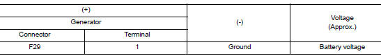
2.CHECK “B” TERMINAL CIRCUIT
Check voltage between generator “B” terminal and ground.
Is the inspection result normal? YES >> GO TO 3.
NO >> Check harness for open between generator and fusible link.
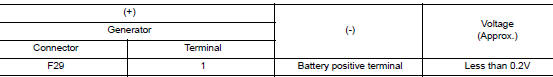
3.CHECK “B” TERMINAL CONNECTION (VOLTAGE DROP TEST)
- Start engine, then engine running at idle and warm.
- Check voltage between battery positive terminal and generator connector “B” terminal.
Is the inspection result normal? YES >> “B” terminal circuit is normal. Refer to CHG-11, "Work Flow (With EXP-800 NI or GR8-1200 NI)" or CHG-14, "Work Flow (Without EXP-800 NI or GR8-1200 NI)".
NO >> Check harness between battery and generator for continuity.
 Power generation voltage variable control system operation
inspection
Power generation voltage variable control system operation
inspection
Diagnosis Procedure
Regarding Wiring Diagram information. Refer to CHG-7, "Wiring Diagram".
CAUTION:
When performing this inspection, always use a charged battery that has completed
the ...
 Symptom diagnosis
CHARGING SYSTEM
Symptom Table
...
Other materials:
Wheel
Inspection
WHEEL
Check tires for wear and improper inflation.
Check wheels for deformation, cracks and other damage. If deformed,
remove wheel and check wheel
runout.
Remove tire from wheel and mount wheel on a balancer machine.
Set dial indicator as shown.
&n ...
Unit removal and installation
ENGINE ASSEMBLY
Exploded view
Engine mounting insulator (RH)
Upper torque rod (RH)
Engine mounting bracket (RH)
Lower torque rod
Torque rod bracket
Engine mounting insulator (LH)
Removal and installation (FWD)
WARNING:
Situate the vehicl ...
C1601 battery power supply
DTC Logic
DTC DETECTION LOGIC
DTC
Display item
Malfunction detected condition
Possible cause
C1601
BATTERY VOLT
When a power supply voltage to the EPS control unit
is maintained at 18.2 V or more or at less than 9 V
continuously for five second ...
