Nissan Rogue Service Manual: C1601 battery power supply
DTC Logic
DTC DETECTION LOGIC
|
DTC |
Display item |
Malfunction detected condition |
Possible cause |
| C1601 | BATTERY VOLT | When a power supply voltage to the EPS control unit is maintained at 18.2 V or more or at less than 9 V continuously for five second or more. |
|
DTC CONFIRMATION PROCEDURE
1.PRECONDITIONING
If ŌĆ£DTC CONFIRMATION PROCEDUREŌĆØ has been previously conducted, always turn ignition switch OFF and wait at least 10 seconds before conducting the next test.
>> GO TO 2.
2.DTC REPRODUCTION PROCEDURE
 With CONSULT
- Turn the ignition switch OFF to ON.
- Perform ŌĆ£EPSŌĆØ self-diagnosis.
Is DTC ŌĆ£C1601ŌĆØ detected? YES >> Proceed to diagnosis procedure. Refer to STC-20, "Diagnosis Procedure".
NO >> Inspection End.
Diagnosis Procedure
Regarding Wiring Diagram information, refer to STC-14, "Wiring Diagram".
1.CHECK EPS CONTROL UNIT GROUND CIRCUIT
- Turn ignition switch OFF.
- Disconnect EPS control unit harness connector.
- Check continuity between EPS control unit harness connector terminal and ground.
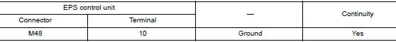
- Connect EPS control unit harness connector.
Is the inspection result normal? YES >> GO TO 2.
NO >> Repair open circuit or short to ground or short to power in harness or connectors.
2.CHECK EPS CONTROL UNIT POWER SUPPLY CIRCUIT (1)
1. Check voltage between EPS control unit harness connector terminals and ground.
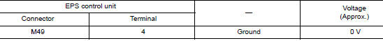
- Turn ignition switch ON.
CAUTION: Never start the engine.
- Check voltage between EPS control unit harness connector and ground.
Is the inspection result normal? YES >> GO TO 4.
NO >> GO TO 3.
3.CHECK EPS CONTROL UNIT POWER SUPPLY CIRCUIT (2)
- Turn ignition switch OFF.
- Check the 10A fuse 30.
- Check the harness for open or short between EPS control unit harness connector terminal 4 and the 10A fuse 30.
Is the inspection result normal? YES >> Perform the trouble diagnosis for ignition power supply circuit. Refer to PG-4, "Wiring Diagram ŌĆö Battery Power Supply ŌĆö".
NO >> Repair or replace malfunctioning parts.
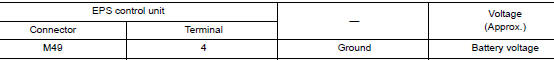
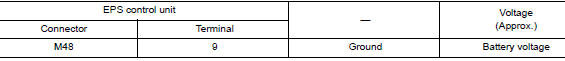
4.CHECK EPS CONTROL UNIT POWER SUPPLY CIRCUIT (3)
- Turn ignition switch OFF.
- Check voltage between EPS control unit harness connector and ground.
- Turn ignition switch ON.
CAUTION: Never start the engine.
- Check voltage between EPS control unit harness connector and ground.
Is the inspection result normal? YES >> GO TO 6.
NO >> GO TO 5.
5.CHECK EPS CONTROL UNIT POWER SUPPLY CIRCUIT (4)
- Turn ignition switch OFF.
- Check the 50A fusible links G and I.
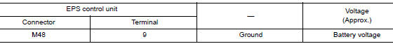
- Check the harness for open or short between EPS control unit harness connector terminal 9 and the 50A fusible links G and I.
Is the inspection result normal? YES >> Perform the trouble diagnosis for power supply circuit. Refer to PG-4, "Wiring Diagram ŌĆö Battery Power Supply ŌĆö".
NO >> Repair or replace malfunctioning parts.
6.CHECK TERMINALS AND HARNESS CONNECTORS
Check the EPS control unit pin terminals for damage or loose connection with harness connector.
Is the inspection result normal? YES >> EPS control unit is malfunctioning. Replace steering column assembly. Refer to STC-36, "Removal and Installation".
NO >> Repair or replace malfunctioning parts.

 C1604 torque sensor
DTC Logic
DTC DETECTION LOGIC
DTC
Display item
Malfunction detected condition
Possible cause
C1604
TORQUE SENSOR
When torque sensor output signal is ma ...
Other materials:
System
INTERIOR ROOM LAMP CONTROL SYSTEM
INTERIOR ROOM LAMP CONTROL SYSTEM : System Description
SYSTEM DIAGRAM
OUTLINE
Interior room lamps* are controlled by interior room lamp timer control
function of BCM.
*: Map lamp and room lamp (when map lamp switch and room lamp switch are in
...
Basic inspection
DIAGNOSIS AND REPAIR WORKFLOW
Work Flow
OVERALL SEQUENCE
DETAILED FLOW
1.GET INFORMATION FOR SYMPTOM
Get detailed information from the customer about the symptom (the
condition and the environment when
the incident/malfunction occurs).
Check operation condition of the ...
Precaution
Precaution for Supplemental Restraint System (SRS) "AIR BAG" and "SEAT
BELT
PRE-TENSIONER"
The Supplemental Restraint System such as ŌĆ£AIR BAGŌĆØ and ŌĆ£SEAT BELT PRE-TENSIONERŌĆØ,
used along
with a front seat belt, helps to reduce the risk or severity of injury to the
...
