Nissan Rogue Service Manual: Upper link
Exploded View
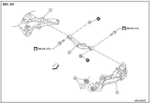
- Rear suspension member
- Upper link
- Rubber washer (LH/RH)
- Rear suspension arm
 Front
Front
Removal and Installation
REMOVAL
- Remove wheel and tire using power tool. Refer to WT-60, "Exploded View"
- Remove rear wheel sensor and harness from rear suspension arm. Refer to
BRC-133, "REAR WHEEL
SENSOR : Exploded View".
CAUTION: Do not pull on rear wheel sensor harness. Refer to BRC-135, "REAR SENSOR ROTOR : Removal and Installation - Rear Sensor Rotor"
- Remove height sensor (if equipped).
- Disconnect harness connector from the height sensor (if equipped). Refer to EXL-271, "Removal and Installation - Rear Height Sensor".
- Set suitable jack under rear suspension arm to relieve the coil spring tension.
- Remove upper link, nut, and bolt from suspension arm with power tool.
- Remove upper link, nut, and bolt from suspension member with power tool.
- Perform the inspection after removal. Refer to RSU-20, "Inspection".
INSTALLATION
Installation is in the reverse order of removal.
- Perform final tightening of rear suspension member and axle installation position under unladen conditions with tires on level ground.
- After installation, perform headlamp initialization. Refer to EXL-223, "Diagnosis Procedure".
- Adjust the neutral position of the steering angle sensor. Refer to BRC-70, "Work Procedure".
- Perform the inspection after installation. Refer to RSU-20, "Inspection".
Inspection
INSPECTION AFTER REMOVAL
Check upper link and bushing for any deformation, cracks, or damage. Replace it if necessary.
INSPECTION AFTER INSTALLATION
Check wheel alignment. Refer to RSU-6, "Inspection".
 Lower link
Exploded View
Rear suspension member
Lower link
Lower link deflector
Rubber washer (LH/RH)
Rear suspension arm
Front
Removal and Installation
REMOVAL
Remove wheel a ...
 Rear stabilizer
Exploded View
Rear stabilizer bar
Connecting rod (RH)
Rear stabilizer bar bushing
Rear stabilizer bar clamp
Connecting rod (LH)
Front
Removal and ...
Other materials:
How to check terminal
CONNECTOR AND TERMINAL PIN KIT
Use the connector and terminal pin kits listed below when
replacing connectors or terminals.
The connector and terminal pin kits contain some of the most
commonly used NISSAN/INFINITI connectors
and terminals. For detailed connector and termin ...
Preparation
Special Service Tool
The actual shape of the tools may differ from those illustrated here.
Tool number
(TechMate No.)
Tool name
Description
—
(J-49286)
Drift and Pull gauge
Measuring drift and pull
Commercial Service Tool
Tool name
...
Power seat switch
Exploded View
Seat cushion outer finisher
Power seat switch
Removal and Installation
REMOVAL
NOTE:
LH shown, RH similar.
Using a suitable tool release clips and remove seat cushion
outer finisher (1).
: Clip
Disconnect harness connector from power seat switch.
...
