Nissan Rogue (T33) 2021-Present Service Manual: System Description :: Component Parts. Power Window System
Power Window System
Component Parts Location
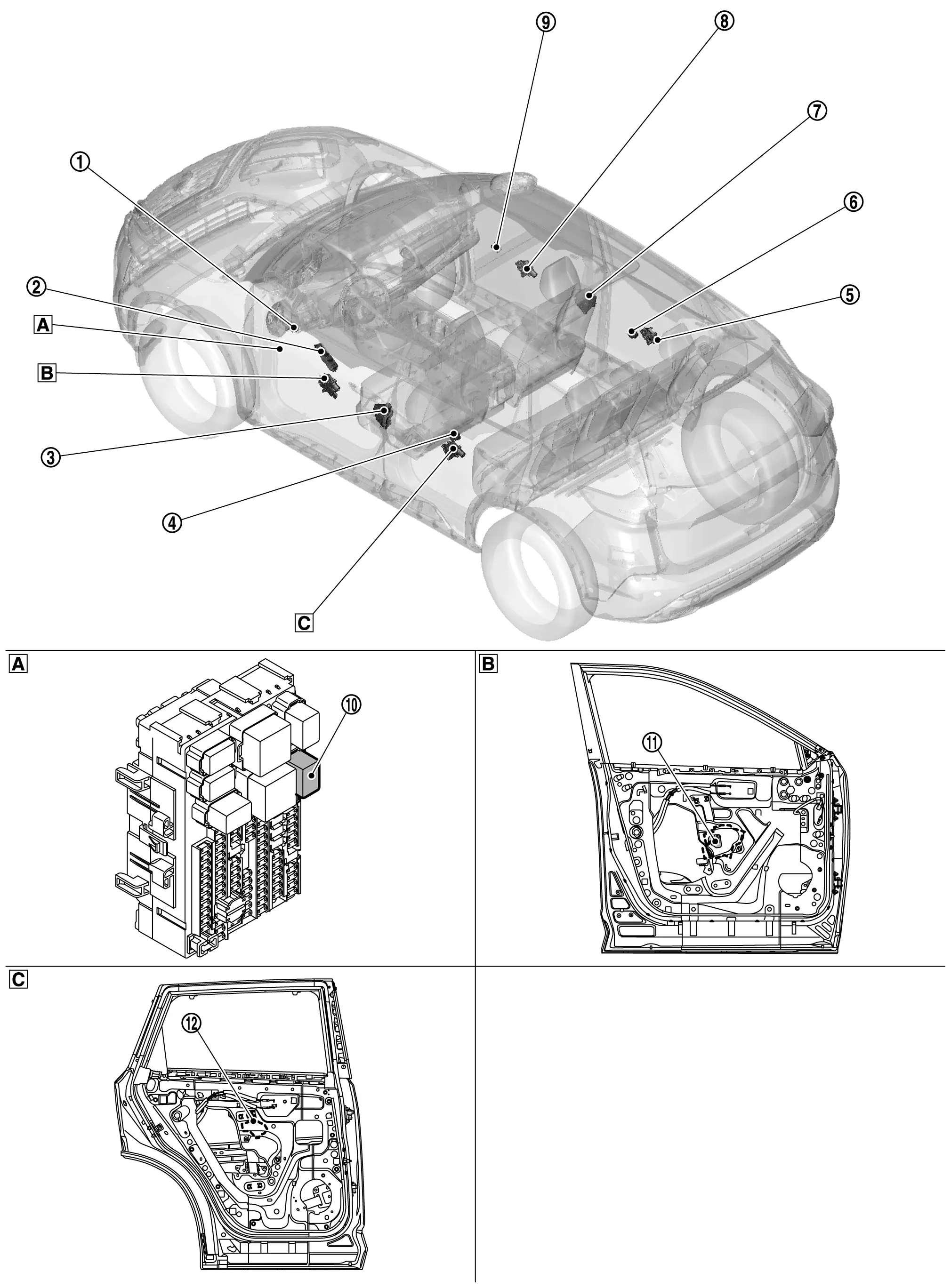
| A. | Fuse block (J/B) | B. | View with front door finisher removed | C. | View with rear door finisher removed |
| No. | Component | Function |
|---|---|---|
| 1. | BCM (Body Control Module) |
|
| 2. | Power window main switch | Refer to Power Window Main Switch. |
| 3. | Front door lock assembly LH (door switch) | Refer to Component Parts Location for detailed component location. |
| 4. | Rear power window switch LH | Refer to Rear Power Window Switch. |
| 5. | Rear power window motor RH | Refer to Rear Power Window Motor. |
| 6. | Rear power window switch RH | Refer to Rear Power Window Switch. |
| 7. | Front door lock assembly RH (door switch) | Refer to Component Parts Location for detailed component location. |
| 8. | Front power window motor (passenger side) | Refer to Front Power Window Motor (Passenger Side). |
| 9. | Front power window switch (passenger side) | Refer to Front Power Window Switch (Passenger side). |
| 10. | Power window relay | Operates the power window system with the control signal from the BCM. Refer to Power Window Relay. |
| 11. | Front power window motor (driver side) | Refer to Front Power Window Motor (Driver Side). |
| 12. | Rear power window motor LH | Refer to Rear Power Window Motor. |
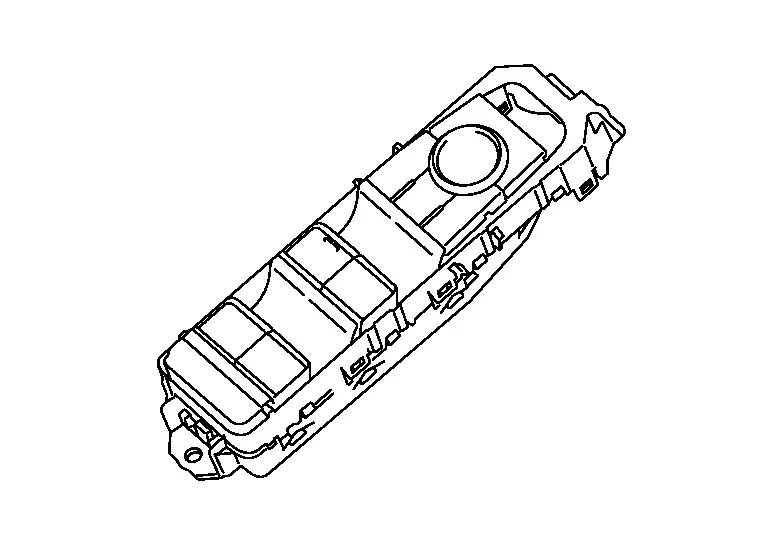
Power Window Main Switch
-
Power window main switch is installed to front door finisher (driver side). Refer to Component Parts Location.
-
Transmits signal to each power window switch and front power window motor (driver side).
-
Turns ON/OFF the power window lock switch.
-
Power window main switch controls all power window motors.
-
Power window lock switch inhibits operation from other power window switches.
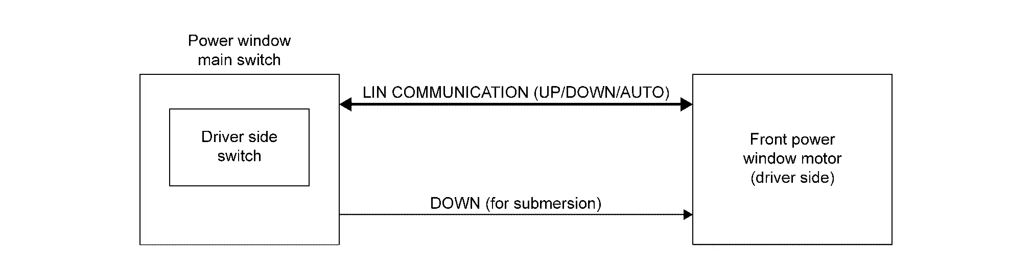
COMPONENT OPERATION
-
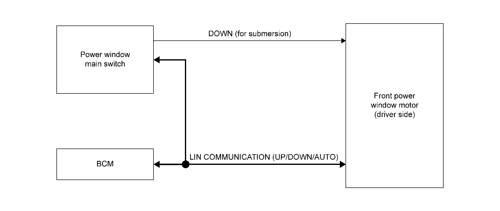
When power window main switch (driver side switch) is operated, it transmits signal to front power window motor (driver side) via LIN communication.
-
When the power window main switch is submerged in water during the Nissan Ariya vehicle is submerged, the UP/DOWN/AUTO control via LIN communication is stopped. Then the DOWN signal circuit between the power window main switch and the front power window motor (driver side) enables only DOWN operation.
-
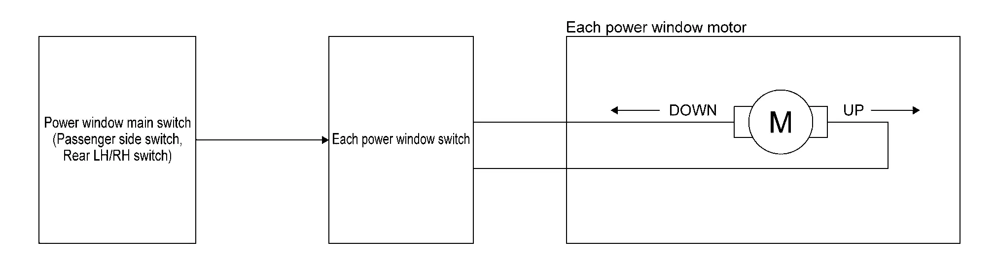
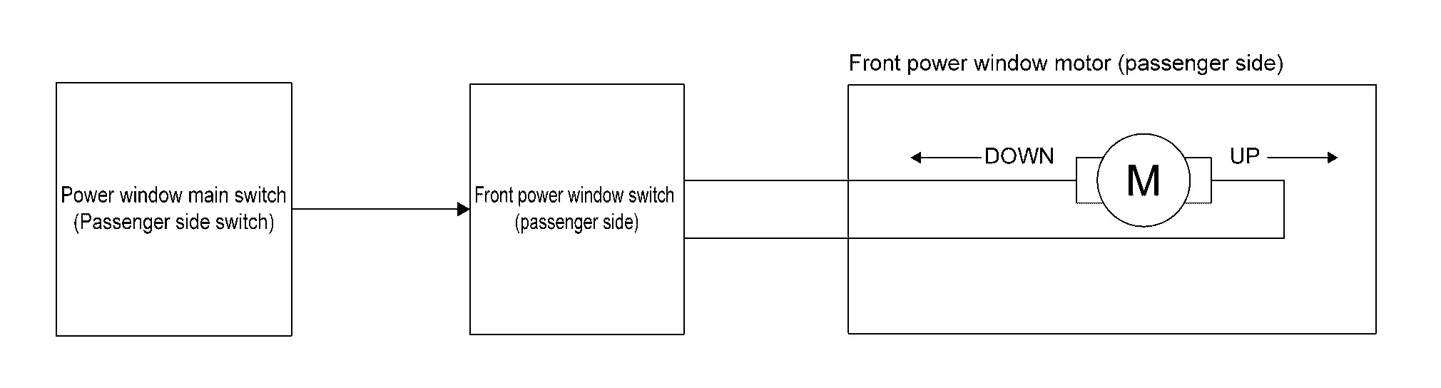
When power window main switch (passenger side switch, rear LH/RH switch) is operated, it transmits signal to each power window motor via each power window switch.
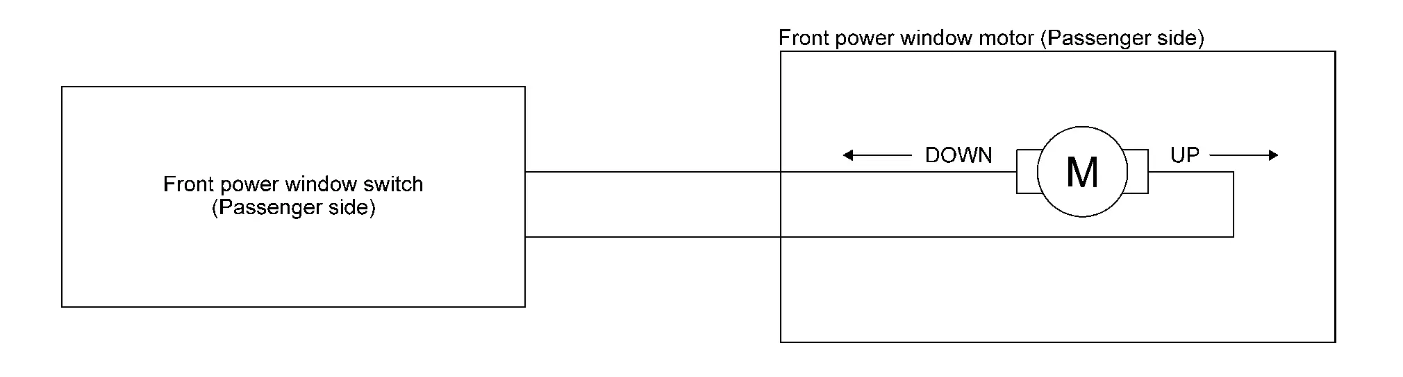
Front Power Window Switch (Passenger side)

-
Front power window switch (passenger side) is installed to front door finisher (passenger side). Refer to Component Parts Location.
-
Front power window switch (passenger side) controls front power window motor (passenger side).
-
Transmits signal to front power window motor (passenger side).
COMPONENT OPERATION
-
When front power window switch (passenger side) is operated, it transmits signal to front power window motor (passenger side).
-
Transmits the operation signal from power window main switch (passenger side switch) to front power window motor (passenger side).
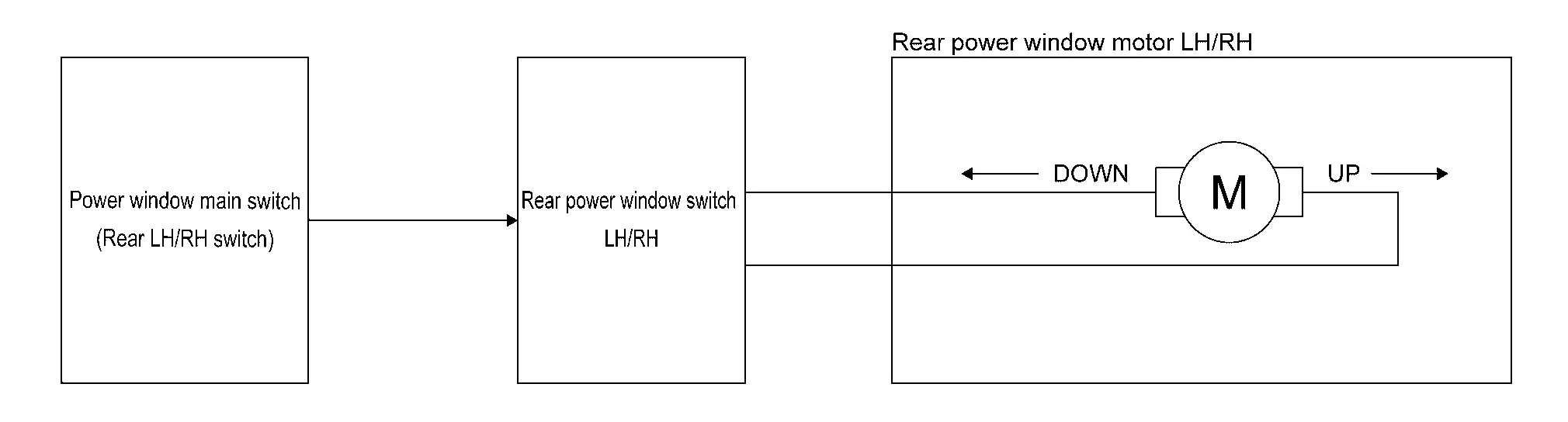
Rear Power Window Switch
-
Rear power window switch is installed to rear door finisher. Refer to Component Parts Location.
-
Rear power window switch LH/RH controls each rear power window motor.
-
Transmits signal to each rear power window motor.
COMPONENT OPERATION
-
When rear power window switch LH/RH is operated, it transmits signal to each rear power window motor.

-
Transmits the operation signal from power window main switch (rear LH/RH switch) to the each rear power window motor.
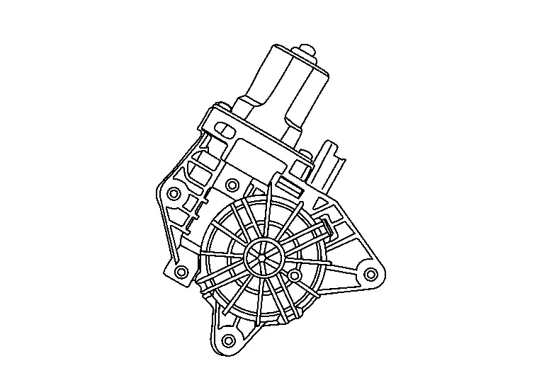
Front Power Window Motor (Driver Side)
-
Front power window motor (driver side) is installed to front door regulator (driver side). Refer to Component Parts Location.
-
Power window motor opens/closes door glass.
-
Power window motor controls AUTO operation.
-
Power window motor controls anti-pinch function.
COMPONENT OPERATION
-
Front power window motor (driver side) receives signal from power window main switch and BCM via LIN communication, then opens/closes door glass.
-
When the power window main switch is submerged in water during the Nissan Ariya vehicle is submerged, the UP/DOWN/AUTO control via LIN communication is stopped. Then the DOWN signal circuit between the power window main switch and the front power window motor (driver side) enables only DOWN operation.
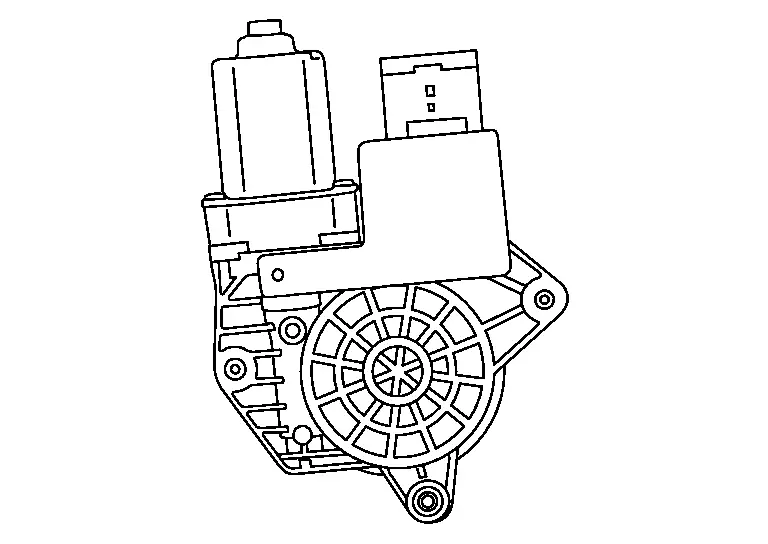
Front Power Window Motor (Passenger Side)
-
Front power window motor (passenger side) is installed to front door regulator (passenger side). Refer to Component Parts Location.
-
The front power window motor (passenger side) opens/closes the passenger side door glass when receiving the UP/DOWN signal from the power window main switch or front power window switch (passenger side).
COMPONENT OPERATION
The front power window motor (passenger side) opens/closes door glass when receiving the UP/DOWN signal from the power window main switch (passenger side switch) or front power window switch (passenger side).
Rear Power Window Motor
-
Rear power window motor is installed to rear door regulator. Refer to Component Parts Location.
-
The rear power window motor LH/RH opens/closes the rear LH/RH door glass when receiving the UP/DOWN signal from the power window main switch (rear LH/RH switch) or rear power window switch LH/RH.
COMPONENT OPERATION
The rear power window motor LH/RH opens/closes door glass when receiving the UP/DOWN signal from the power window main switch (rear LH/RH switch) or rear power window switch LH/RH.
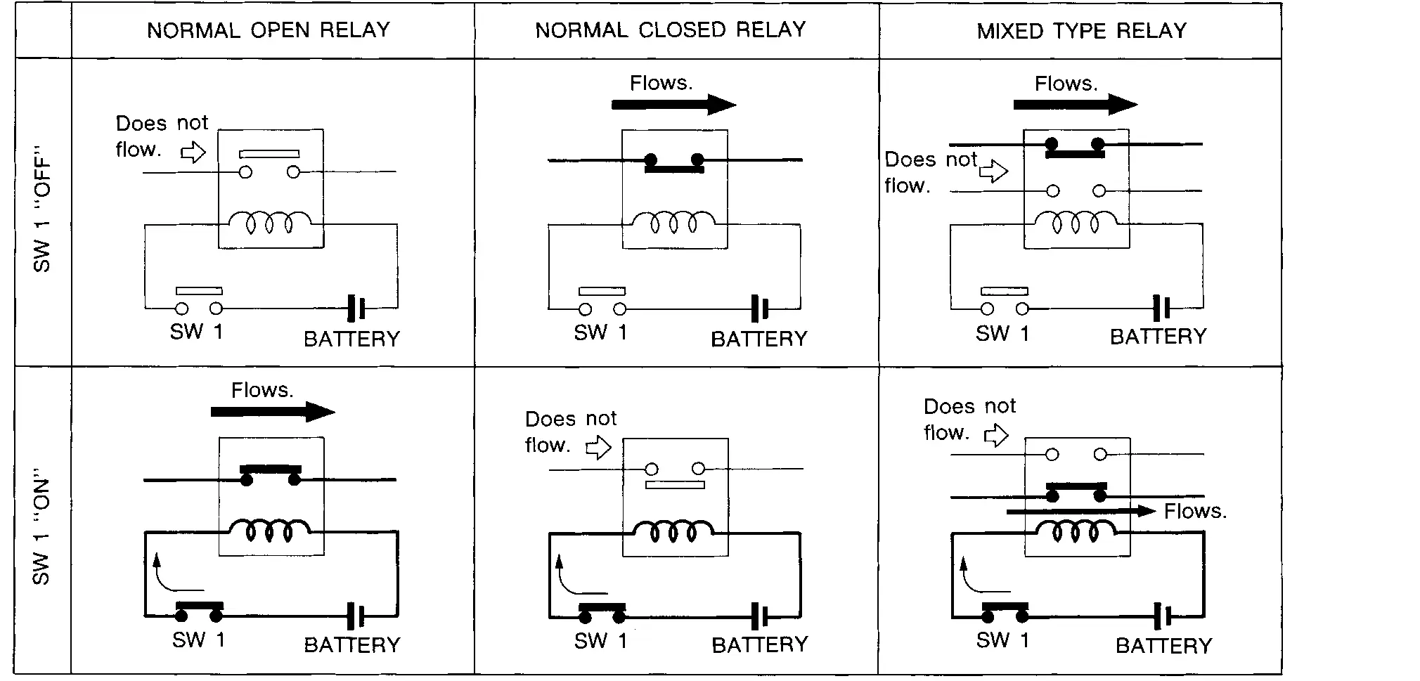
Power Window Relay
-
The power window relay is installed to fuse block (J/B). Refer to Component Parts Location.
-
This relay is controlled by BCM. When it turns ON, power is supplied to the power window system.
COMPONENT OPERATION
The power window relay utilizes a normal open relay.
Other materials:
U2140-87 Can Comm Err (ecm)
DTC Description
DESCRIPTIONCAN (Controller Area Network) is a serial
communication line for real time applications. It is an on-Nissan Ariya
vehicle multiplex communication line with high data communication speed
and excellent error detection ability. Modern Nissan Ariya vehicle is
equipped ...
Head Up Display (HUD)
Basic information
Example
Example
WARNING
Failure to correctly adjust the brightness or position of the HUD image may reduce visibility through the windshield, which could lead to an accident resulting in serious injury or death.
Avoid focusing on the Head Up Display (HUD) for extended per ...
Informations relatives aux capacités de charge du véhicule
Informations de base
AVERTISSEMENT
Il est extrêmement dangereux de voyager dans le compartiment à bagages d’un véhicule Nissan Rogue. En cas de collision, les personnes se trouvant dans cette zone sont exposées à un risque très élevé de blessures graves, voire mortelles.
...