Nissan Rogue Service Manual: System description
COMPONENT PARTS
Component Parts Location
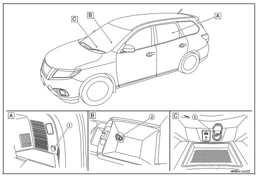
- Luggage side lower finisher RH
- Center console
- Cluster lid C
- Rear cargo power socket
- Console power socket
- Front power socket
 Precaution
Precaution for Supplemental Restraint System (SRS) "AIR BAG" and "SEAT
BELT
PRE-TENSIONER"
The Supplemental Restraint System such as “AIR BAG” and “SEAT BELT PRE-TENSIONE ...
 Wiring diagram
POWER SOCKET
Wiring Diagram
...
Other materials:
Approach warning
Approach warning
NOTE:
The warning chime may sound and the FCW
indicator may blink when the distance sensor
detects vehicles in other lanes A or
objects on the side of the road A . This may
cause the FCW system to operate inappropriately.
The distance sensor may detect
these objects wh ...
P0132 A/F sensor 1
DTC Description
DTC DETECTION LOGIC
To judge the malfunction, the diagnosis checks that the A/F signal computed
by ECM from the A/F sensor 1
signal is not inordinately high.
DTC No.
CONSULT screen terms
(Trouble diagnosis content)
DTC detecting condition
P0132
A/F S ...
Rear wiper arm
Exploded View
Rear wiper motor
Rear wiper arm
Rear wiper blade
Rear wiper arm cover
Seal
Removal and Installation
REMOVAL
Check that the rear wiper is in the auto stop position.
Remove the rear wiper arm cover.
Remove the rear wiper arm nut from ...
