Nissan Rogue Service Manual: Component parts
Component Parts Location
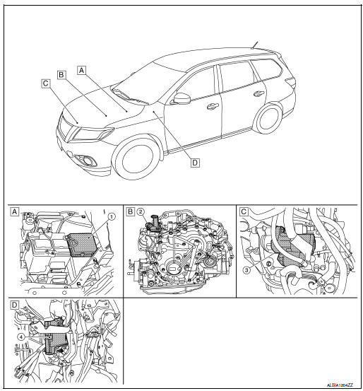
- Engine room (RH)
- View with transmission removed
- View with engine and transmission removed
- Behind instrument panel (LH)
| No. | Component part | Description |
| 1 | IPDM E/R | CPU inside IPDM E/R operates the starter relay when the ignition switch is in the start position. |
| 2 | Transmission range switch | Transmission range switch supplies power to the starter relay and starter control relay inside the IPDM E/R when the selector lever is shifted to the P (Park) or N (Neutral) position. |
| 3 | Starter motor | The starter motor plunger closes and the motor is supplied with battery power, which in turn cranks the engine, when the S terminals supplied with electric power. |
| 4 | BCM | BCM controls the starter relay inside IPDM E/R. |

 System
System Description
The starter motor plunger closes and provides a closed circuit between the
battery and the starter motor. The
starter motor is grounded to the cylinder block. With power and gro ...
Other materials:
VDC warning lamp
Component Function Check
1.CHECK VDC WARNING LAMP FUNCTION
Check that VDC warning lamp in combination meter turns ON for 1 second after
ignition switch is turned ON.
CAUTION:
Never start the engine.
Is the inspection result normal?
YES >> Inspection End.
NO >> Proceed to BRC ...
Vehicle phonebook
To access the vehicle phonebook:
Press the button on
the control panel.
Touch the “Phonebook” key.
Choose the desired entry from the displayed
list.
The number of the entry will be displayed on
the screen. Touch the number to initiate dialing.
NOTE:
...
Rear-facing child restraint installation using the seat belts
Rear-facing child restraint installation using the seat belts
WARNINGThe three-point seat belt with Automatic
Locking Retractor (ALR) must be used
when installing a child restraint. Failure to
use the ALR mode will result in the child
restraint not being properly secured. The ...
