Nissan Rogue Service Manual: System description
COMPONENT PARTS
POWER DOOR LOCK SYSTEM
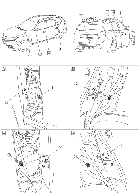
POWER DOOR LOCK SYSTEM : Component Parts Location
|
No |
Component |
Function |
| 1 | BCM | Controls the door lock system. Refer to BCS-7, "BODY CONTROL SYSTEM : Component Parts Location" for detailed installation location |
| 2 | Main power window and door lock/unlock switch | DLK-22, "Door Lock and Unlock Switch (Driver Side)" |
| 3 | Front door switch LH | Back door lock assembly (door ajar switch) |
| 4 | Front door lock assembly LH | DLK-25, "Front Door Lock Assembly (LH)" |
| 5 | Rear door switch LH | DLK-25, "Rear Door Switch" |
| 6 | Rear door lock actuator LH | Rear door lock actuator locks/unlocks the rear door latch assembly. |
| 7 | Front power window and door lock/unlock switch RH | DLK-22, "Door Lock and Unlock Switch (Passenger Side)" |
| 8 | Front door switch RH | DLK-24, "Front Door Switch" |
| 9 | Front door lock actuator RH | Rear door lock actuator locks/unlocks the rear door latch assembly. |
| 10 | Rear door switch RH | DLK-25, "Rear Door Switch" |
| 11 | Rear door lock actuator RH | Rear door lock actuator locks/unlocks the rear door latch assembly. |
| 12 | Back door lock assembly (door ajar switch) | DLK-21, "Back Door Lock Assembly" |
INTELLIGENT KEY SYSTEM
INTELLIGENT KEY SYSTEM : Component Parts Location
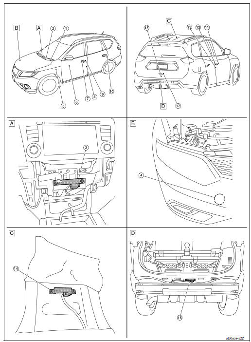
- View with A/C Switch (auto A/C) or front air control (manual A/C) assembly removed
- View of center of rear floor behind console
- View with rear bumper fascia removed
|
No. |
Component |
Function |
| 1 | Combination meter | Combination meter transmits the vehicle speed signal to BCM via CAN
communication. BCM also receives the vehicle speed signal from ABS actuator and electric unit (control unit) via CAN communication. BCM compares both signals to detect the vehicle speed. Security indicator lamp is located on combination meter. Security indicator lamp blinks when ignition switch is in any position other than ON to warn that NISSAN VEHICLE IMMOBILIZER SYSTEM-NATS [NVIS (NATS)] is on board. Refer to MWI-6, "METER SYSTEM : Component Parts Location". |
| 2 | Push-button ignition switch | Push-button ignition switch has push switch inside which detects that push-button ignition switch is pressed, and then transmits ON/OFF signal to BCM. BCM changes the ignition switch position with the operation of push-button ignition switch. BCM maintains the ignition switch position status while push-button ignition switch is not operated. |
| 3 | Inside key antenna (instrument center) | Inside key antenna (instrument center) detects whether Intelligent
Key is inside
the vehicle or not, and then transmits the signal to the BCM. Refer to DLK-22, "Inside Key Antenna (Instrument Center)". |
| 4 | Intelligent Key warning buzzer | Intelligent Key warning buzzer warns the user, who is outside the vehicle, of operation confirmation according to Intelligent Key operation and door request switch operation, or of an inappropriate operation. |
| 5 | BCM | BCM controls INTELLIGENT KEY SYSTEM (ENGINE START FUNCTION),
NISSAN VEHICLE IMMOBILIZER SYSTEM-NATS [NVIS (NATS)] and VEHICLE
SECURITY SYSTEM. BCM performs the ID verification between BCM and Intelligent Key when the Intelligent Key is carried into the detection area of inside key antenna, and pushbutton ignition switch is pressed. If the ID verification result is OK, ignition switch operation is available. Then, when the ignition switch is turned ON, BCM performs ID verification between BCM and ECM. If the ID verification result is OK, ECM can start engine. Refer to BCS-7, "BODY CONTROL SYSTEM : Component Parts Location" for detailed installation location. |
| 6 | Main power window and door lock/unlock switch | Door lock and unlock switch is integrated into the power window main
switch. Door lock and unlock switch transmits door lock/unlock operation signal to BCM. Refer to PWC-7, "Power Window Main Switch". |
| 7 | Outside key antenna LH | Outside key antenna (LH) detects whether Intelligent Key is outside
the vehicle
or not, and then transmits the signal to the BCM. Refer to DLK-23, "Outside Key Antenna (LH)". |
| 8 | Front door lock assembly LH | Door key cylinder switch is integrated into front door lock assembly
(driver side). Door key cylinder switch detects door LOCK/UNLOCK operation using mechanical key, and then transmits the operation signal to BCM. Refer to DLK-25, "Front Door Lock Assembly (LH)". |
| 9 | Door request switch LH | Door request switch transmits door lock/unlock request signal to the BCM. |
| 10 | Rear door lock actuator LH | Rear door lock actuator locks/unlocks the rear door latch assembly. |
| 11 | Outside key antenna RH | Outside key antenna (RH) detects whether Intelligent Key is outside
the vehicle
or not, and then transmits the signal to the BCM. Refer to DLK-23, "Outside Key Antenna (RH)". |
| 12 | Door request switch RH | Door request switch transmits door lock/unlock request signal to the BCM. |
| 13 | Door switch RH | Door switch detects door open/close condition and then transmits ON/OFF signal to BCM. |
| 14 | Inside key antenna (console) | Inside key antenna (console) detects whether Intelligent Key is
inside the vehicle
or not, and then transmits the signal to the BCM. Refer to DLK-23, "Inside Key Antenna (Console)". |
| 15 | Back door lock assembly | Back door lock actuator locks/unlocks the back door latch assembly. |
| 16 | Outside key antenna (rear bumper) | Outside key antenna (Rear bumper) detects whether Intelligent Key is
outside
the vehicle or not, and then transmits the signal to the BCM. Refer to DLK-23, "Outside Key Antenna (Rear Bumper)". |
| 17 | Back door opener switch | Back door request switch transmits door lock/unlock request signal to the BCM. |
INTEGRATED HOMELINK TRANSMITTER
INTEGRATED HOMELINK TRANSMITTER : Component Parts Location

|
No. |
Component |
Function |
|
1 |
Auto anti-dazzling inside mirror | DLK-25, "Integrated Homelink Transmitter" |
AUTOMATIC BACK DOOR SYSTEM
AUTOMATIC BACK DOOR SYSTEM : Component Parts Location
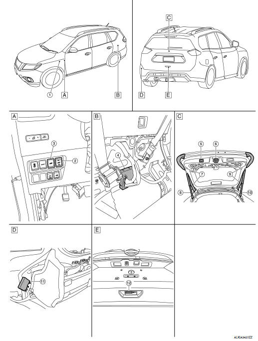
- View of LH side of instrument panel
- View with luggage side lower finisher removed
- View of back door open
- View with rear fascia removed
- View of back door
|
No. |
Component |
Function |
| 1 | BCM | Transmits and receives signal to the automatic back door control module Refer to BCS-7, "BODY CONTROL SYSTEM : Component Parts Location" for detailed installation location |
| 2 | Automatic back door main switch | DLK-21, "Automatic Door Main Switch" |
| 3 | Automatic back door switch | DLK-21, "Automatic Back Door Switch" |
| 4 | Automatic back door control module | DLK-21, "Automatic Back Door Control Module" |
| 5 | Automatic back door close switch | DLK-21, "Automatic Back Door Close Switch" |
| 6 | Back door lock assembly | DLK-21, "Back Door Lock Assembly" |
| 7 | Touch sensor LH | DLK-21, "Back Door Touch Sensor" |
| 8 | Spindle unit LH | DLK-25, "Spindle Unit" |
| 9 | Touch sensor RH | DLK-21, "Back Door Touch Sensor" |
| 10 | Spindle unit RH | DLK-25, "Spindle Unit" |
| 11 | Automatic back door warning buzzer | DLK-21, "Automatic Back Door Warning Buzzer" |
| 12 | Back door opener switch | DLK-21, "Automatic Back Door Opener Switch" |
Automatic Back Door Control Module
Automatic back door control unit: Controls the automatic back door system.
Automatic Back Door Switch
Detects open/close operation of automatic back door
Automatic Door Main Switch
- Controls automatic open/close operation of each switches.
- Transmits automatic door main switch signal to automatic back door control module.
Automatic Back Door Warning Buzzer
Warns the user of the automatic back door condition and inappropriate operations with the buzzer sounds
Automatic Back Door Close Switch
- Detects close operation of automatic back door.
- Transmits automatic back door close switch signal to automatic back door control module.
Back Door Lock Assembly
Back door closure motor, half latch switch, open switch, close switch and back door switch are installed.
- Closure motor: Inputs open/close signal from automatic back door control module and activates the back door auto closure operation.
- Half latch switch: Starts the closure motor close operation.
- Open switch: Stops the closure motor open operation.
- Close switch: Stops the closure motor close operation.
- Back door switch: Inputs back door open/ close condition to BCM.
Automatic Back Door Opener Switch
Door switch detects open/close status of door and transmits door switch signal to BCM.
- Detects open operation of automatic back door.
- Transmits automatic back door opener switch signal to automatic back door control module.
Back Door Touch Sensor
During back door close operation, the touch sensor detects any trapped foreign material.
Back Door Opener Switch
- Back door opener switch (1) transmits back door opener switch signal to BCM.
- Back door opener switch (1) is integrated in outside handle (back door).
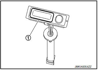
Back Door Request Switch
- Back door request switch (1) transmits back door request switch signal to BCM.
- Back door request switch (1) is integrated in outside handle (back door).
Door Lock and Unlock Switch (Driver Side)
- Door lock and unlock switch transmits door lock/unlock signal operation to BCM.
- Door lock and unlock switch is Integrated in the power window main switch.
Door Lock and Unlock Switch (Passenger Side)
- Door lock and unlock switch transmits door lock/unlock signal operation to BCM.
- Door lock and unlock switch is Integrated in the front power window switch (passenger side).
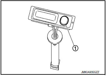
Inside Key Antenna (Instrument Center)
- Inside key antenna (instrument center) detects that Intelligent Key is within the inside detection area, and then transmits detection status to BCM.
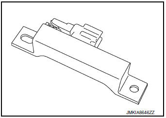
Inside Key Antenna (Console)
- Inside key antenna (console) detects that Intelligent Key is within the inside detection area, and then transmits detection status to BCM.
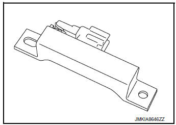
Outside Key Antenna (Rear Bumper)
- Outside key antenna (rear bumper) detects that Intelligent Key is within the outside detection area, and then transmits detection status to BCM. Request signal is transmitted simultaneously to Intelligent Key.
- Outside key antenna (rear bumper) is installed in the rear of rear bumper.
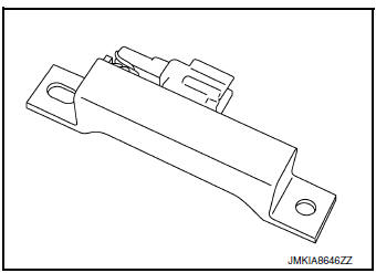
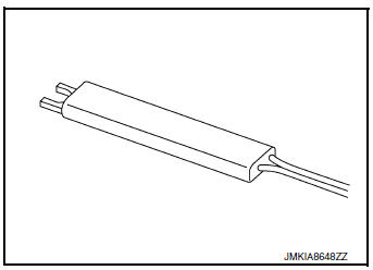
Outside Key Antenna (LH)
- Outside key antenna (LH) detects that Intelligent Key is within the outside detection area, and then transmits detection status to BCM. Request signal is transmitted simultaneously to Intelligent Key.
- Outside key antenna (LH) is installed in driver side outside handle.
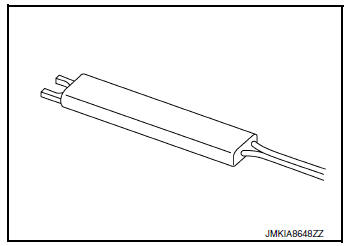
Outside Key Antenna (RH)
- Outside key antenna (RH) detects that Intelligent Key is within the outside detection area, and then transmits detection status to BCM. Request signal is transmitted simultaneously to Intelligent Key.
- Outside key antenna (RH) is installed in passenger side outside handle.
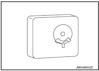
Intelligent Key Warning Buzzer
- Intelligent Key warning buzzer warns the user, who is outside vehicle, of operation confirmation according to Intelligent Key operation and door request switch operation, or of an inappropriate operation.
- Intelligent Key warning buzzer is installed in the rear of front bumper and behind RH headlight.
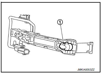
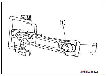
Front Door Request Switch (LH)
- Front door request switch (LH) transmits door request switch signal to BCM.
- Front door request switch (LH) (1) is integrated in driver side outside handle.
Front Door Request Switch (RH)
- Front door request switch (RH) transmits door request switch signal to BCM.
- Front door request switch (RH) (1) is integrated in passenger side outside handle.
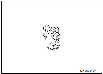
Front Door Switch
Door switch detects open/close status of door and transmits door switch signal to BCM.
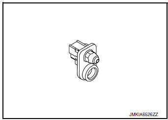
Rear Door Switch
Door switch detects open/close status of door and transmits door switch signal to BCM.
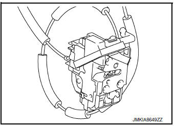
Front Door Lock Assembly (LH)
- Door lock actuator and unlock sensor are Integrated in driver door lock assembly.
- Door lock actuator receives lock/unlock signal from BCM, and then locks/unlocks driver door.
- Only front door lock assembly (driver side) integrates unlock
sensor.
Unlock sensor transmits lock/unlock status of driver seat to BCM.
Spindle Unit
Encoder and spindle motor are installed:
- Encoder: Automatic back door control module receives the pulse signals from encoders A and B that occurred due to synchronization with the back door operation. The automatic back door control module calculates the back door position, operation direction, and operation speed according to the received pulse signals.
- Spindle motor: Inputs open/close signal from automatic back door control module and activates the automatic back door open/close operation.
Integrated Homelink Transmitter
Within the Homelink transmitter a maximum of 3 radio signals can be stored and transmitted to operate the garage door, etc.
SYSTEM (POWER DOOR LOCK SYSTEM)
System Diagram
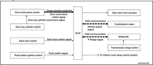
System Description
DOOR LOCK FUNCTION
Door Lock and Unlock Switch
- The door lock and unlock switch (driver side) is built into power window main switch.
- The door lock and unlock switch (passenger side) is built into front power window switch (passenger side).
- Interlocked with the locking operation of door lock and unlock switch, door lock actuators of all doors are locked.
- Interlocked with the unlocking operation of door lock and unlock switch, door lock actuators of all doors actuator are unlocked.
Door Key Cylinder Switch
- With the mechanical key inserted in the door key cylinder on driver side, turning it to lock position locks door lock actuator of all doors.
- With the mechanical key inserted in the door key cylinder on
driver side, turning it to unlock position once
unlocks the driver side door, turning it to unlock position again within 60
seconds after the first unlock operation
unlocks all of the other doors. (SELECTIVE UNLOCK OPERATION)
Selective unlock operation mode can be changed using CONSULT.
Refer to BCS-17, "DOOR LOCK : CONSULT Function (BCM - DOOR LOCK)".
IGNITION POSITION WARNING FUNCTION
When door lock and unlock switch are operated while driver side door is open and ignition position is ACC or ON, door locks once but immediately unlocks.
INTERIOR ROOM LAMP CONTROL FUNCTION
Interior room lamp is controlled according to door lock/unlock state, refer to INL-7, "INTERIOR ROOM LAMP CONTROL SYSTEM : System Description".
AUTOMATIC DOOR LOCK/UNLOCK FUNCTION (LOCK OPERATION)
The interlock door lock function is the function that locks all doors linked with the vehicle speed or shift position.
It has 2 types as per the following items.
Vehicle Speed Sensing Auto Door Lock
All doors are locked when the vehicle speed reaches 24 km/h (15 MPH) or more.
BCM outputs the lock signal to all door lock actuators when it detects that the ignition switch is turned ON, all doors are closed and the vehicle speed received from the combination meter via CAN communication becomes 24 km/h (15 MPH) or more.
P Range Interlock Door Lock
All doors are locked when shifting the selector lever from the P (Park) position to any position other than P (Park).
BCM outputs the lock signal to all door lock actuators when it detects that the ignition switch is in the ON position, all doors are closed and the shift signal received from the park position switch when shifted from the P (Park) position to any position other than P (Park).
Setting change of Automatic Door Lock/Unlock Function The lock operation setting of the automatic door lock/unlock function can be changed.
 With CONSULT
The ON/OFF switching of the automatic door lock function and the type selection of the automatic door lock/ unlock function can be performed at the WORK SUPPORT setting of CONSULT.
 Without CONSULT
The automatic door lock function ON/OFF can be switched by performing the following operation.
- Close all doors (door switch OFF)
- Ignition switch: OFF→ON
- Press and hold the door lock and unlock switch for 5 seconds or more in the lock direction within 20 seconds after turning the ignition switch ON.
- The switching complete when the hazard lamp blinks.
OFF → ON : 2 blinks
ON → OFF : 1 blink
AUTOMATIC DOOR LOCK/UNLOCK FUNCTION (UNLOCK OPERATION)
The automatic door lock/unlock function is the function that unlocks all doors linked with the key position or shift position. It has 2 types as per the following items.
IGN OFF Interlock Door Unlock All doors are unlocked when the power supply position is changed from ON to OFF.
BCM outputs the unlock signal to all door lock actuators when it detects that the power supply position is changed from ignition switch ON to OFF.
P Range Interlock Door Unlock
All doors are unlocked when shifting the selector lever from any position other than P to the P position.
BCM outputs the unlock signal to all door lock actuators when it detects that the ignition switch is in the ON position and the shift signal received from park position switch when shifted from any position other than P to the P position.
Setting change of Automatic Door Lock/Unlock Function
The unlock operation setting of the automatic door lock/unlock function can be changed.
 With CONSULT
The ON/OFF switching of the automatic door lock/unlock function and the type selection of the automatic door lock/unlock function can be performed at the WORK SUPPORT setting of CONSULT.
 Without CONSULT
The automatic door lock/unlock function ON/OFF can be switched by performing the following operation.
- Close all doors (door switch OFF)
- Ignition switch: OFF→ON
- Press and hold the door lock and unlock switch for 5 seconds or more in the unlock direction within 20 seconds after turning the power supply position ON.
- The switching is complete when the hazard lamp blinks.
OFF → ON : 2 blinks
ON → OFF : 1 blink
SYSTEM (INTELLIGENT KEY SYSTEM)
INTELLIGENT KEY SYSTEM
INTELLIGENT KEY SYSTEM : System Diagram
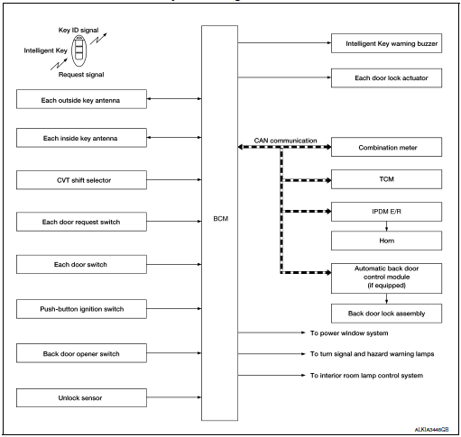
INTELLIGENT KEY SYSTEM : System Description
- The Intelligent Key system is a system that makes it possible to lock
and unlock the door locks (door lock/
unlock function) by carrying the Intelligent Key, which operates based on
the results of electronic ID verification
using two-way communication between the Intelligent Key and the vehicle (BCM).
CAUTION: The driver should always carry the Intelligent Key.
- The settings for each function can be changed with CONSULT.
- If an Intelligent Key is lost, a new Intelligent Key can be registered. A maximum of 4 Intelligent Keys can be registered.
- It is possible to perform a diagnosis on the system and register an Intelligent Key with CONSULT.
|
Function |
Description |
Refer |
| Door lock | Lock/unlock can be performed by pressing the request switch. | DLK-28 |
| Back door opener | The back door can be opened by carrying the Intelligent Key and pressing the back door opener switch. | DLK-31 |
| Remote keyless entry | Lock/unlock can be performed by pressing the remote controller button of the Intelligent Key. | DLK-29 |
| Key reminder | The key reminder buzzer sounds a warning if the door is locked with the key left inside the vehicle. | DLK-35 |
| Warning | If an action that does not meet the operating condition of the Intelligent Key system is taken, the buzzer sounds to inform the driver. | DLK-35 |
| Interior room lamp control | Interior room lamp is controlled according to door lock/unlock state. | DLK-28 |
| Panic alarm | When Intelligent Key panic alarm button is pressed, horn sounds. | DLK-35 |
DOOR LOCK FUNCTION
DOOR LOCK FUNCTION : System Diagram
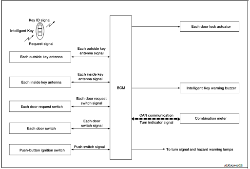
DOOR LOCK FUNCTION : System Description
Only when pressing the door request switch it is possible to lock and unlock the door by carrying the Intelligent Key.
OPERATION DESCRIPTION
- When the BCM detects that each door request switch is pressed, it activates the outside key antenna and inside key antenna corresponding to the pressed door request switch and transmits the request signal to the Intelligent Key. Then check that the Intelligent Key is near the door.
- If the Intelligent Key is within the outside key antenna detection area, it receives the request signal and transmits the key ID signal to the BCM.
- BCM receives the key ID signal and compares it with the registered key ID.
- BCM locks/unlocks each doors (except back door).
- BCM sounds Intelligent Key warning buzzer (lock: 2 times, unlock: 1 time) and blinks hazard warning lamps (lock: 2 times, unlock: 1 time) at the same time as a reminder.
OPERATION CONDITION
If the following conditions are satisfied, door lock/unlock operation is performed if the door request switch is operated.
|
Each door request switch operation |
Operation condition |
| Lock |
|
| Unlock |
|
*: Even with a registered Intelligent Key remaining inside the vehicle, door locks can be locked/unlocked from outside of the vehicle with a spare Intelligent Key as long as key IDs are different.
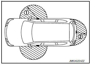
OUTSIDE KEY ANTENNA DETECTION AREA
The outside key antenna detection area of door lock/unlock function is in the range of approximately 80 cm (31.50 in) surrounding the driver, passenger door handles (1) and back door handle (2). However, this operating range depends on the ambient conditions.
SELECTIVE UNLOCK FUNCTION
Lock Operation
When a LOCK signal is sent from door request switch (driver side, passenger side, back door), all doors are locked.
Unlock Operation
- When an UNLOCK signal from driver side door request switch is
transmitted, driver side door are unlocked.
When another UNLOCK signal is transmitted within 60 seconds, all other doors (except back door) are unlocked.
- When an UNLOCK signal from passenger side door request switch is transmitted, passenger side door is unlocked. When another UNLOCK signal is transmitted within 60 seconds, all other doors (except back door) are unlocked.
- When an UNLOCK signal from back door request switch is
transmitted, back door open permission is set.
When another UNLOCK signal is transmitted within 60 seconds, all doors (except back door) are unlocked.
How To Change Selective Unlock Operation Mode Selective unlock operation mode can be changed using CONSULT.
Refer to BCS-21, "INTELLIGENT KEY : CONSULT Function (BCM - INTELLIGENT KEY)".
HAZARD AND BUZZER REMINDER FUNCTION
During lock or unlock operation by each door request switch, the hazard warning lamps and Intelligent Key warning buzzer blinks or honks as a reminder.
Operating Function Of Hazard And buzzer Reminder
|
Operation |
Hazard warning lamp blinks |
Intelligent Key warning buzzer honks |
| Unlock | Once | Once |
| Lock | Twice | Twice |
Hazard and buzzer reminder does not operate in the following conditions.
- Ignition switch position is ON.
- Door is open (only lock operation).
How To Change Hazard And Buzzer Reminder Mode Hazard and buzzer reminder mode can be changed using CONSULT.
Refer to BCS-21, "INTELLIGENT KEY : CONSULT Function (BCM - INTELLIGENT KEY)".
AUTO DOOR LOCK FUNCTION
After door is unlocked by door request switch operation and if 60 seconds or more passes without performing the following operation, all doors are automatically locked. However, operation check function does not activate.
| Operating condition |
|
How To Change Auto Door Lock Operation Mode
Auto door lock operation mode can be changed using CONSULT.
Refer to BCS-21, "INTELLIGENT KEY : CONSULT Function (BCM - INTELLIGENT KEY)".
LIST OF OPERATION RELATED PARTS
Parts marked with Ă— are the parts related to operation.
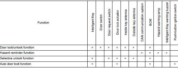
BACK DOOR OPEN FUNCTION
BACK DOOR OPEN FUNCTION : System Diagram
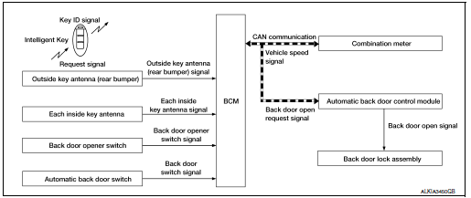
BACK DOOR OPEN FUNCTION : System Description
This section describes the operation of the back door opener switch.
- The back door open function can open the back door by pressing the back door opener switch while carrying the Intelligent Key and all doors (except back door) are locked.
- The back door open function enables the back door to be opened by pressing back door opener switch after BCM transmits UNLOCK signal to each door.
BACK DOOR OPEN
While back door open in the permitted state, back door opens when back door opener switch is pressed after back door request switch is operated. Back door open also can be operated according to the following procedure.
- When the BCM detects that back door opener switch is pressed, it activates the outside key antenna (rear bumper) and inside key antenna and transmits the request signal to the Intelligent Key and then, checks that the Intelligent Key is near the back door.
- If the Intelligent Key is within the outside key antenna detection area, it receives the request signal and transmits the key ID signal to the BCM.
- BCM receives the key ID signal and compares it with the registered key ID.
- If the verification result is OK, BCM transmits the back door open request signal to automatic back door control module via CAN communication.
- Automatic back door control module transmits back door open request signal to back door lock assembly and back door is open.
- When the back door is open, automatic back door system performs
waiting operation for next back door
close operation.
The operation of then back door open is the same as the automatic back door system, refer to DLK-39, "System Description".
OPERATION CONDITION
If the following conditions are not satisfied, back door open operation is not performed even if the back door opener switch is operated.
|
Back door opener switch operation |
Operation condition |
| Back door open |
|
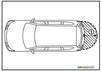
OUTSIDE KEY ANTENNA DETECTION AREA
The outside key antenna detection area of back door open function is in the range of approximately 80 cm (31.50 in) surrounding the outside key antenna (rear bumper) (1). However, this operating range depends on the ambient conditions.
LIST OF OPERATION RELATED PARTS
Parts marked with Ă— are the parts related to operation.
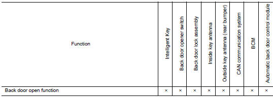
REMOTE KEYLESS ENTRY FUNCTION
REMOTE KEYLESS ENTRY FUNCTION : System Diagram
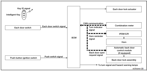
REMOTE KEYLESS ENTRY FUNCTION : System Description
The Intelligent Key has the same functions as the remote control entry system. Therefore, it can be used in the same manner as the remote controller by operating the door lock/unlock button.
OPERATION
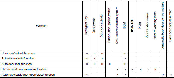
Remote keyless entry system controls operation of the following items.
- Door lock/unlock function
- Selective unlock function
- Auto door lock function
- Hazard and horn reminder function
- Automatic back door open/close function
OPERATION AREA
The remote engine start operating range is approximately 60 m (197 ft) from the vehicle.
DOOR LOCK/UNLOCK FUNCTION
- When door lock/unlock button of the Intelligent Key is pressed, lock signal or unlock signal transmitted from Intelligent Key to BCM.
- When BCM receives the door lock/unlock signal, it operates all door lock actuators, blinks the hazard lamp (lock: 2 time, unlock: 1 times) and horn chirp signal to IPDM E/R at the same time as a reminder.
- IPDM E/R honks horn (lock: 1 time) as a reminder.
OPERATION CONDITION
If the following condition are satisfied, remote keyless entry operation is performed when the Intelligent Key is operated.
|
Remote controller operation |
Operation condition |
| Lock |
|
| Unlock | Panic alarm is not activated. |
SELECTIVE UNLOCK FUNCTION
- When a LOCK signal is transmitted from Intelligent Key, all doors are locked.
- When an UNLOCK signal is transmitted from Intelligent Key once, driver side door are unlocked.
- Then, if an UNLOCK signal is transmitted from Intelligent Key again within 60 seconds, all other doors (except for back door) are unlocked.
How to change selective unlock operation mode.
Selective unlock operation mode can be changed using CONSULT.
Refer to BCS-17, "DOOR LOCK : CONSULT Function (BCM - DOOR LOCK)".
AUTO DOOR LOCK FUNCTION
After door is unlocked by Intelligent Key button operation and if 60 seconds or more passes without performing the following operation, all doors are locked. However, operation check function does not activate.
| Operating condition |
|
How to change auto door lock operation mode.
Auto door lock mode can be changed using CONSULT.
Refer to BCS-21, "INTELLIGENT KEY : CONSULT Function (BCM - INTELLIGENT KEY)".
HAZARD AND HORN REMINDER FUNCTION
When doors are locked or unlocked by Intelligent Key, BCM blinks hazard warning lamps as a reminder.
The hazard and horn reminder has a horn chirp mode (C mode) and a non-horn chirp mode (S mode).
Operating Function of Hazard and Horn Reminder

Hazard and horn reminder does not operate in the following conditions.
- Ignition switch position is ON.
- Door is open (only lock operation).
How to Change Hazard and Horn Reminder Mode
 With CONSULT
Hazard and horn reminder operation mode can be changed using CONSULT.
Refer to BCS-21, "INTELLIGENT KEY : CONSULT Function (BCM - INTELLIGENT KEY)".
 Without CONSULT
When LOCK and UNLOCK signals are sent from the Intelligent Key for more than 2 seconds at the same time, the hazard and horn reminder mode is changed and hazard warning lamp blinks and horn sounds as per the following items:

AUTOMATIC BACK DOOR OPEN/CLOSE FUNCTION
When back door button of Intelligent Key is pressed for 0.4 second or more, back door open automatically for detailed description, refer to DLK-39, "System Description".
LIST OF OPERATION RELATED PARTS
Parts marked with Ă— are the parts related to operation.
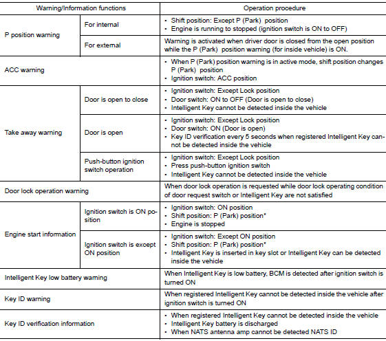
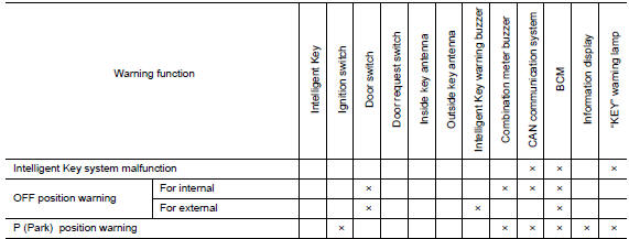
WARNING FUNCTION
WARNING FUNCTION : System Description
OPERATION DESCRIPTION
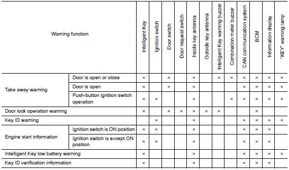
The warning function are as per the following items and are given to the user as warning information and warnings using combinations of Intelligent Key warning buzzer, combination meter buzzer, KEY warning lamp and information display in combination meter.
- Intelligent Key system malfunction
- OFF position warning
- P position warning
- Take away warning
- Door lock operation warning
- Engine start information
- Intelligent Key low battery warning
- Key ID warning
- Key ID verification information
OPERATION CONDITION
Once the following condition from below is established, alert or warning is executed.
|
Warning/Information functions |
Operation procedure |
|
| Intelligent Key system malfunction | When a malfunction is detected on BCM, “KEY” warning lamp illuminates. | |
| OFF position warning | For internal | When condition A, B or condition C is satisfied
|
| For external | OFF position warning (For internal) is in active mode, driver side
door is
closed. NOTE: OFF position (For external) active only when each of the sequence occurs as below: P position warning → ACC warning → OFF position warning (For internal) → OFF position warning (For internal) |
|
WARNING METHOD
The following table shows the alarm or warning methods with chime.
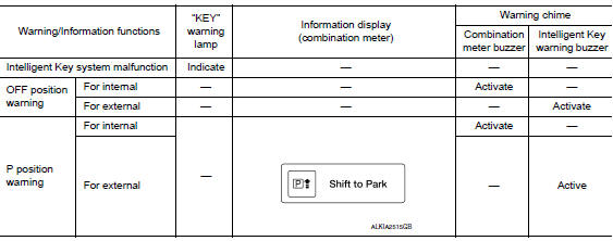
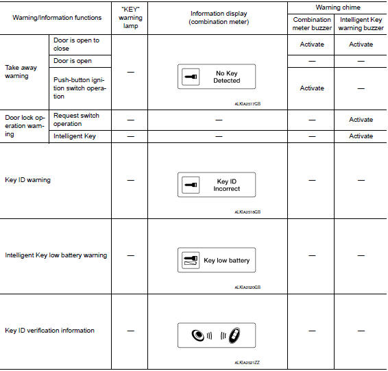
LIST OF OPERATION RELATED PARTS
Parts marked with Ă— are the parts related to operation.
SYSTEM (AUTOMATIC BACK DOOR SYSTEM)
System Diagram
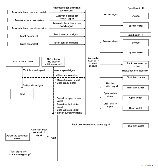
System Description
The automatic back door system performs the automatic open/close operation of the back door by operating the automatic back door switch, the automatic back door close switch, the back door opener switch, and Intelligent Key.
AUTOMATIC BACK DOOR OPEN/CLOSE FUNCTION
- e case of the back door fully closed, operate the automatic back door switch, Intelligent Key or back door opener switch with the back door unlock. The back door closure motor releases the latch, then the spindle motor opens the back door to the fully open position. The closure motor reverses to the neutral position simultaneously.
- In the case of the back door fully open, operate the automatic back door switch, Intelligent Key or automatic back door close switch. The spindle motor closes the back door to the half-latch position, then the back door closure motor to the full latch position. Then, the closure motor reverses to the neutral position.
AUTOMATIC OPEN/CLOSE TEMPORARY STOP FUNCTION
Automatic open/close temporary stop function temporarily stops the open/close operation by operating back door opener switch during automatic open/close operation or by turning automatic back door main switch OFF.
Back Door Opener Switch Operation
- Automatic open/close operation stops when back door opener switch is operated during automatic open/ close operation.
- Back door performs automatic open operation in an open direction when back door opener switch is operated again during automatic open/close temporary stop function operation.
- Back door performs automatic close operation in a close direction when automatic back door close switch is operated during automatic open/close temporary stop function operation.
- Automatic operation is performed again, in the direction that automatic back door switch operated before stopping, when automatic back door switch or Intelligent Key button is operated during automatic open/close temporary stop function operation.
Automatic Back Door Main Switch Operation
- While automatic back door main switch is ON, automatic open/close operation stops when automatic back door main switch is turned OFF during automatic open/close operation.
- While automatic back door main switch is OFF, automatic open/close operation stops when automatic back door main switch is turned ON then turned OFF during automatic open/close operation
- Back door performs automatic open operation in an open direction when back door opener switch is operated again during auto open/close temporary stop function operation.
- Back door performs automatic close operation in a close direction when automatic back door close switch is operated during automatic open/close temporary stop function operation.
- Automatic operation is performed again, in the direction that automatic back door switch operated before stopping, when automatic back door switch or Intelligent Key button is operated during automatic open/close temporary stop function operation.
BACK DOOR OPEN POSITION SETTING FUNCTION
Back door open position setting function enables a user to set stop position for automatic open operation.
Setting Procedure
Stop position for back door open position setting function can be set by the following procedure.
- Manually move the back door to a stop setting position.
- Press and hold the automatic back door close switch for 3 seconds while maintaining the back door position.
- The switching is complete when the buzzer sounds (pattern E).
- Fully close the back door.
Cancellation Procedure
Setting of back door open position setting function can be cancelled by the following procedure.
- Manually move the back door to a fully open position.
- Press and hold the automatic back door close switch for 3 seconds.
- The switching is complete when the buzzer sounds (pattern E).
- Fully close the back door.
BACK DOOR AUTO CLOSURE FUNCTION
Open Function
When back door opener switch is pressed and automatic back door main switch in the OFF position, BCM transmits the back door open request signal to automatic back door control module via CAN communication, and automatic back door control module opens back door lock assembly.
Closure Function
When the back door is closed to the half-latch position, the motor drives to rotate the latch lever and pulls it in from half latched to fully latched and automatically closes the door. Then, the closure motor reverses to the neutral position.
WARNING FUNCTION
The warning function is as follows and gives the user warning information using automatic back door warning chime and hazard warning lamps.
Chime Operation Condition
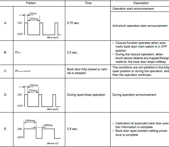
ANTI-PINCH FUNCTION
During auto open operation, if an object is detected by encoder pulse in the door's path, a warning chime sounds and the back door operates in the reverse direction to prevent pinching.
During auto close operation, if an object is detected by the touch sensors and encoder pulse in the door's path, a warning chime sounds and the back door operates in the open direction until it is fully open.
Operation Condition
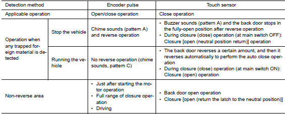

AUTOMATIC BACK DOOR OPEN/CLOSE OPERATION CONDITION
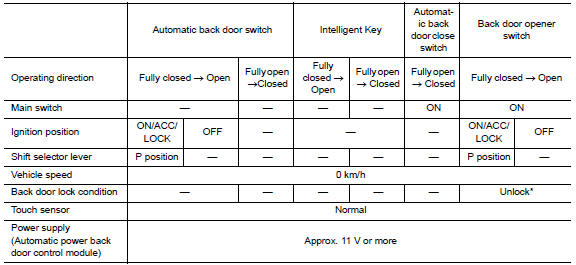
*: If the registered Intelligent Key is used, the operation can be performed even if the back door is in the LOCK position.
CONTROL IF NOT WITHIN THE OPERATION CONDITIONS DURING THE OPERATION
If the back door is not within the operation conditions during the operation, the automatic back door control module performs the control as follows.

TIME CHART FOR AUTOMATIC BACK DOOR SYSTEM
Fully Closed to Fully Open Operation When operating the automatic back door switch, automatic back door opener switch and Intelligent Key in the fully closed position, the system operates as follows.
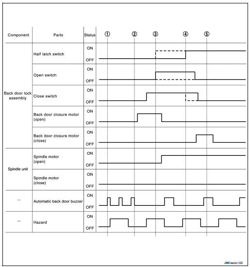
- Operates the chime and hazard after the operation enable conditions are established.
- The back door closure motor performs the open operation after the chime (pattern A) stops sounding.
- Stops the back door closure motor open operation after turning the open switch to ON Then, operate the spindle motor to perform the back door open operation.
- The back door closure motor performs the close operation after turning the half latch switch to ON.
- Stop the back door closure motor close operation and return the latch to the neutral position after turning the close switch to OFF.
NOTE: In the operation of steps 3 and 4, the inputs of half latch switch, open switch, and close switch may be different according to the reaction force of the back door weatherstrip. Refer to the area encircled by a broken line in the Time chart (fully closed to fully open operation).
Fully Open to Fully Closed Operation
When operating the automatic back door switch, automatic back door close switch and Intelligent Key, the automatic back door system operates as follows.
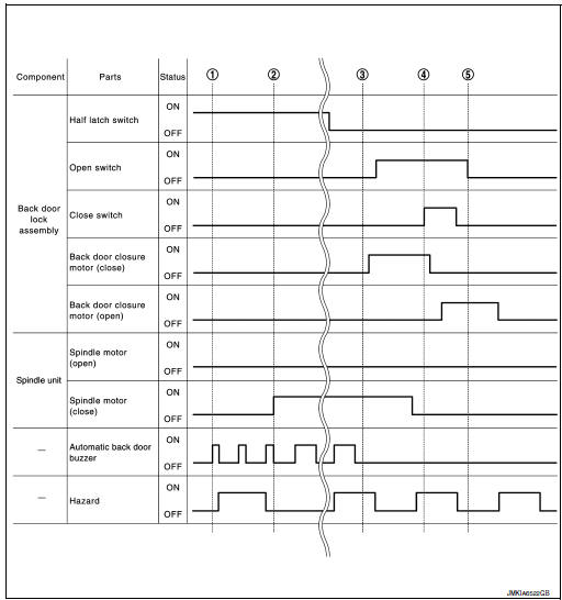
- Operates the chime and hazard after the operation enable conditions are established.
- After the chime (pattern A) stops sounding, operates the spindle motor to perform the back door close operation.
- The back door closure motor performs the close operation in 300 msec. or more after turning the half latch switch to OFF.
- The back door closure motor performs the open operation after turning the close switch to ON.
- Stop the back door closure motor open operation and return the latch to the neutral position after turning the close switch to OFF.
SYSTEM (INTEGRATED HOMELINK TRANSMITTER)
System Description
|
Item |
Function |
| Integrated Homelink® transmitter | A maximum of 3 radio signals can be stored and transmitted to operate the garage door, etc. |
DIAGNOSIS SYSTEM (BCM)
COMMON ITEM
COMMON ITEM : CONSULT Function (BCM - COMMON ITEM)
APPLICATION ITEM
CONSULT performs the following functions via CAN communication with BCM.
|
Direct Diagnostic Mode |
Description |
| Ecu Identification | The BCM part number is displayed |
| Self Diagnostic Result | The BCM self diagnostic results are displayed. |
| Data Monitor | The BCM input/output data is displayed in real time. |
| Active Test | The BCM activates outputs to test components. |
| Work support | The BCM activates outputs to test components. |
| Configuration |
|
| CAN Diag Support Mntr | The result of transmit/receive diagnosis of CAN communication is displayed. |
SYSTEM APPLICATION
BCM can perform the following functions.
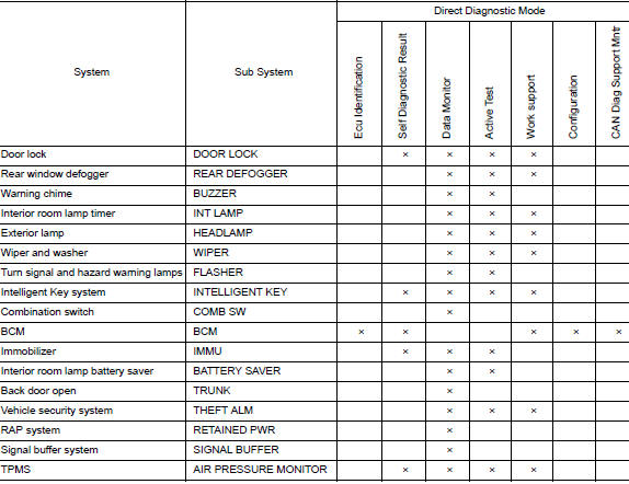
DOOR LOCK
DOOR LOCK : CONSULT Function (BCM - DOOR LOCK)
SELF DIAGNOSTIC RESULT
Refer to BCS-48, "DTC Index".
DATA MONITOR
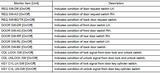
ACTIVE TEST

WORK SUPPORT
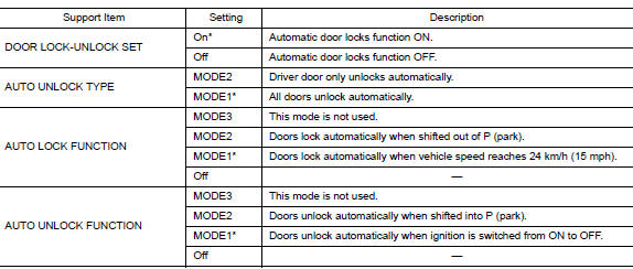
* : Initial setting
INTELLIGENT KEY
INTELLIGENT KEY : CONSULT Function (BCM - INTELLIGENT KEY)
SELF DIAGNOSTIC RESULT
Refer to BCS-48, "DTC Index".
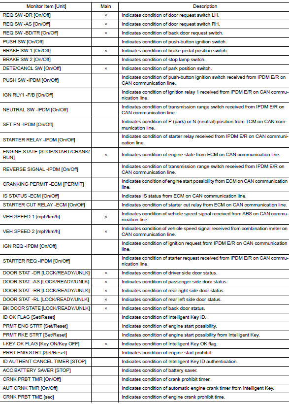
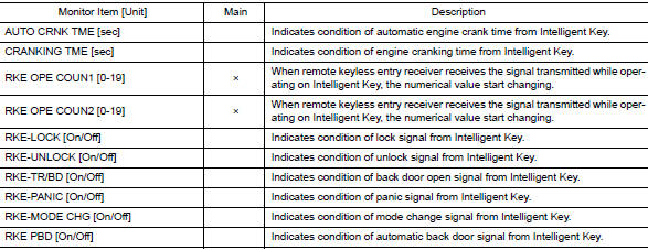
DATA MONITOR
ACTIVE TEST

WORK SUPPORT

TRUNK
TRUNK : CONSULT Function (BCM - TRUNK)
DATA MONITOR

DIAGNOSIS SYSTEM (AUTOMATIC BACK DOOR CONTROL UNIT)
CONSULT Function
APPLICATION ITEMS
CONSULT performs the following functions via CAN communication with automatic back door control module.

SELF DIAGNOSTIC RESULTS
Refer to DLK-57, "DTC Index".
DATA MONITOR


WORK SUPPORT

 Preparation
Special Service Tool
The actual shapes of the tools may differ from those illustrated here.
Tool number
(TechMate No.)
Tool name
Description
—
(J-39570)
Chassis ...
 ECU diagnosis information
AUTOMATIC BACK DOOR CONTROL UNIT
Reference Value
VALUES ON THE DIAGNOSIS TOOL
CONSULT MONITOR ITEM
TERMINAL LAYOUT
PHYSICAL VALUES
Fail Safe
DTC Inspection Prior ...
Other materials:
Washer switch
Description
Washer switch is integrated with the combination switch.
Combination switch (wiper and washer switch) switches polarity
between front washer operating and rear
washer operating to supply power and ground to the front and rear washer
motor.
Component Inspection
...
Around View® Monitor (if so equipped)
With the ignition switch in the ON position, press
the CAMERA button or move the shift lever to the
R (Reverse) position to operate the Around View
Monitor. The monitor displays various views of
the position of the vehicle in a split screen format.
WARNING
The Around View Monit ...
P0444, P0445 EVAP canister purge volume control solenoid
DTC Description
DTC DETECTION LOGIC
DTC No.
CONSULT screen terms
(Trouble diagnosis content)
DTC detecting condition
P0444
PURG VOLUME CONT/V
(Evaporative emission system purge control
valve circuit open)
An excessively low voltage signal is sent to ECM through ...
