Nissan Rogue Service Manual: Shift lock system
Component Function Check
1.CHECK SHIFT LOCK OPERATION (PART 1)
- Turn ignition ON.
- Shift the selector lever to “P” position.
- Attempt to shift the selector lever to any other than position with the brake pedal released.
Can the selector lever be shifted to any other position? YES >> Go to TM-183, "Diagnosis Procedure".
NO >> GO TO 2.
2.CHECK SHIFT LOCK OPERATION (PART 2)
Attempt to shift the selector lever to any other than position with the brake pedal depressed.
Can the selector lever be shifted to any other position? YES >> Inspection End.
NO >> Go to TM-183, "Diagnosis Procedure".
Diagnosis Procedure
Regarding Wiring Diagram information, refer to TM-75, "Wiring Diagram".
1.CHECK STOP LAMP SWITCH
- Ignition switch ON.
- Check voltage between stop lamp switch connector E38 terminal 4 and ground.
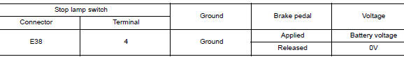
Is the inspection result normal? YES >> GO TO 2.
NO >> GO TO 4.
2.CHECK CVT SHIFT SELECTOR
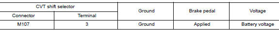
Check voltage between CVT shift selector connector M107 terminal 4 and ground.
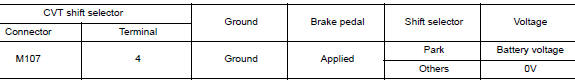
Is the inspection result normal? YES >> GO TO 3.
NO >> GO TO 5.
3.CHECK GROUND CIRCUIT
- Ignition switch OFF.
- Disconnect CVT shift selector connector.
- Check continuity between CVT shift selector connector M107 terminal 4 and ground.
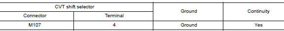
Is the inspection result normal? YES >> Replace CVT shift selector. Refer to TM-194, "Removal and Installation".
NO >> Repair or replace harness.
4.CHECK STOP LAMP SWITCH POWER CIRCUIT
Check voltage between stop lamp switch connector E38 terminal 3 and ground.
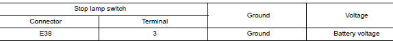
Is the inspection result normal? YES >> Replace stop lamp switch. Refer to BR-20, "Exploded View".
NO >> Repair or replace harness.
5.CHECK CVT SHIFT SELECTOR POWER CIRCUIT
Check voltage between CVT shift selector connector M107 terminal 3 and ground.
Is the inspection result normal? YES >> Replace CVT shift selector. Refer to TM-194, "Removal and Installation".
NO >> Repair or replace harness or connector.
Component Inspection (CVT Shift Selector Assembly)
1.CHECK CVT SHIFT SELECTOR ASSEMBLY (PART 1)
Check continuity between CVT shift selector connector terminals.
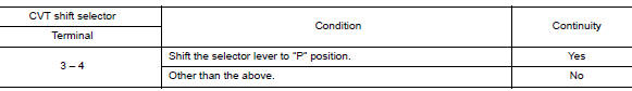
Is the inspection result normal? YES >> GO TO 2.
NO >> Replace CVT shift selector assembly. Refer to TM-194, "Removal and Installation".
2.CHECK CVT SHIFT SELECTOR ASSEMBLY (PART 2)
Apply voltage to terminals of CVT shift selector and check that shift lock solenoid is activated.
CAUTION:
- Connect the fuse between the terminals when applying the voltage.
- Never cause shorting between terminals.
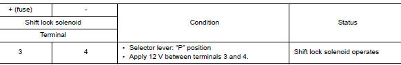
Is the inspection result normal? YES >> Inspection End NO >> Replace CVT shift selector assembly. Refer to TM-194, "Removal and Installation".
Component Inspection (Stop Lamp Switch)
1.CHECK STOP LAMP SWITCH
Check continuity between the stop lamp switch connector terminals.
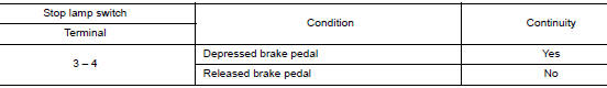
Is the inspection result normal? YES >> Inspection End.
NO >> Replace stop lamp switch. Refer to BR-20, "Exploded View".
 Shift position indicator circuit
Component Parts Function Inspection
1.CHECK SHIFT POSITION INDICATOR
Start the engine.
Shift selector lever.
Check that the selector lever position and the shift position
...
 Symptom diagnosis
CVT CONTROL SYSTEM
Symptom Table
The diagnosis item number indicates the order of check. Start checking
in the order from 1.
Perform diagnoses of symptom table 1 before symptom table 2 ...
Other materials:
The fuel gauge does not move
Description
Fuel gauge does not move from a certain position.
Diagnosis Procedure
1.CONDUCTING THE COMBINATION METER SELF-DIAGNOSIS MODE
Perform the self-diagnosis mode of combination meter, and then check that the
fuel gauge operates normally.
Refer to MWI-19, "Description".
I ...
Oil pan and oil strainer
Exploded View
Oil pan, upper
Oil filter
Front cover
O-ring
Oil strainer
Oil pan, lower
Washer
Drain plug
O-ring
Oil level gauge guide
Oil level gauge
Rear cover plate
To Oil pan, lower
Removal and In ...
P0863 TCM communication
DTC Description
DTC DETECTION LOGIC
DTC
CONSULT screen terms
(Trouble diagnosis content)
DTC detection condition
P0863
CONTROL UNIT (CAN)
(TCM Communication Circuit)
An error is detected at the initial CAN diagnosis of TCM.
POSSIBLE CAUSE
TCM
FAIL-SAFE
...
