Nissan Rogue Service Manual: Service data and specifications (SDS)
General Specification
GENERAL SPECIFICATIONS
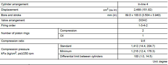
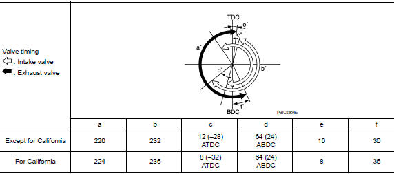
( ): Valve timing control ŌĆ£ONŌĆØ
Drive belt

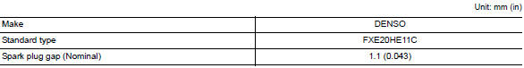
Spark Plug
Intake Manifold

Exhaust Manifold

Camshaft
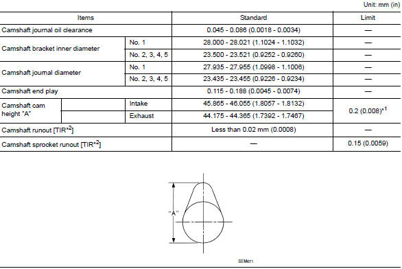
*1: Cam wear limit
*2: Total indicator reading
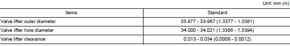
VALVE LIFTER
VALVE CLEARANCE
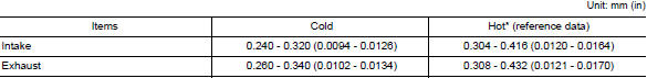
*: Approximately 80┬░C (176┬░F)
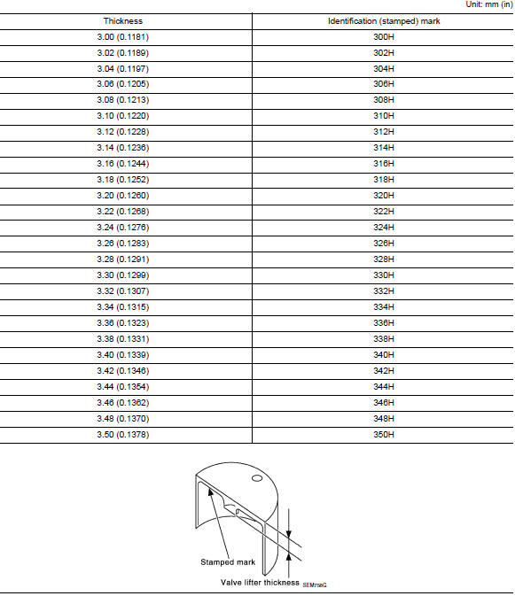
AVAILABLE VALVE LIFTER
Cylinder Head
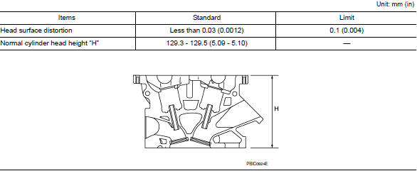
CYLINDER HEAD
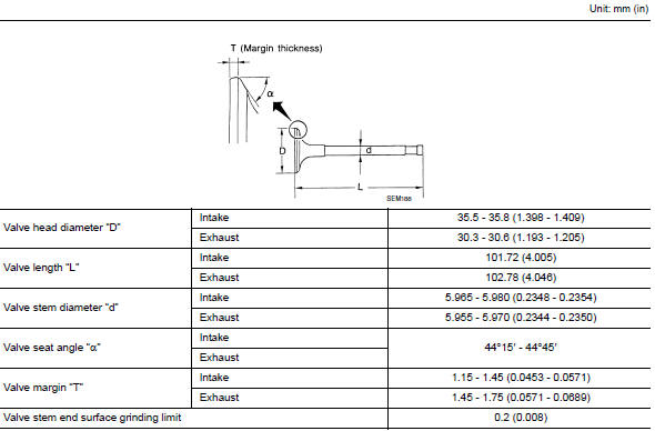
VALVE DIMENSIONS
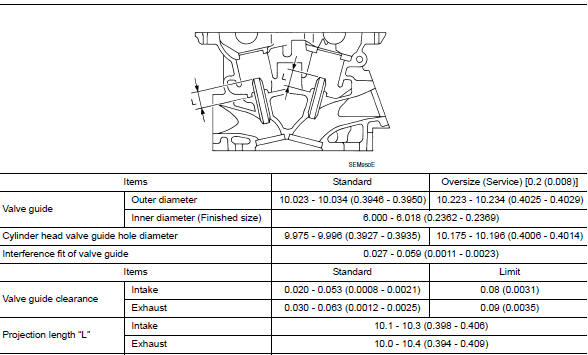
VALVE GUIDE
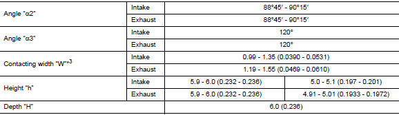
VALVE SEAT
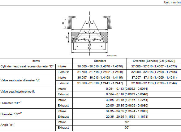
*1: Diameter made by intersection point of conic angles ŌĆ£α1ŌĆØ and ŌĆ£α2ŌĆØ
*2: Diameter made by intersection point of conic angles ŌĆ£α2ŌĆØ and ŌĆ£α3ŌĆØ
*3: Machining data
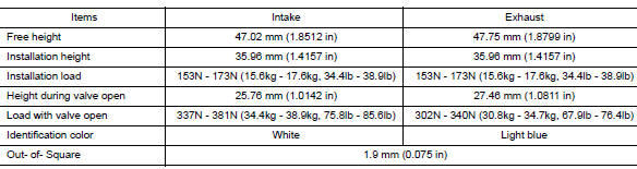
VALVE SPRING
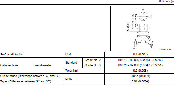
Cylinder Block
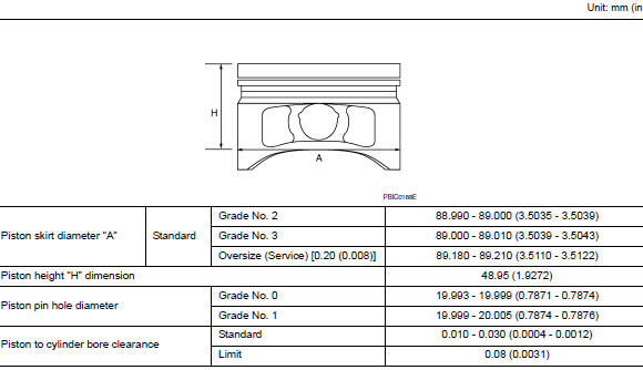
AVAILABLE PISTON
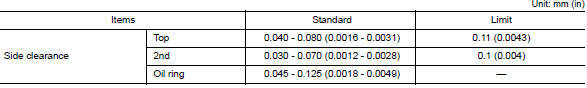
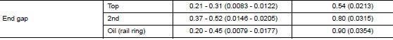
PISTON RING
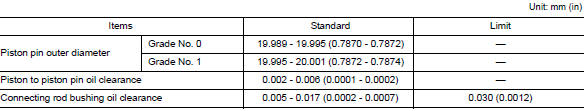
PISTON PIN
CONNECTING ROD
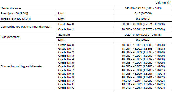
*: After installing in connecting rod
CRANKSHAFT
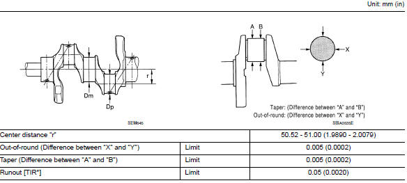
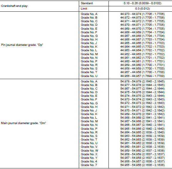
*: Total indicator reading
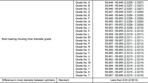
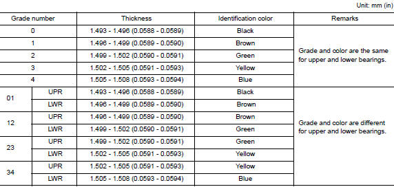
Main Bearing
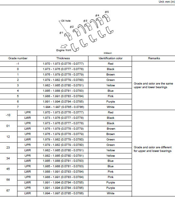
UNDERSIZE

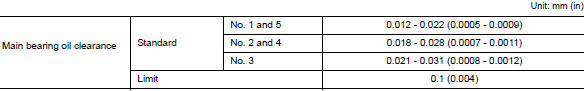
MAIN BEARING OIL CLEARANCE
Connecting Rod Bearing
UNDERSIZE

CONNECTING ROD BEARING OIL CLEARANCE

 How to select piston and bearing
DESCRIPTION
Selection points
Selection parts
Selection items
Selection methods
Between cylinder block to
crankshaft
Main bearing
Main bearing grade (bearing
thick ...

Other materials:
Doors
When the doors are locked using one of the
following methods, the doors cannot be opened
using the inside or outside door handles. The
doors must be unlocked to open the doors.
WARNING
Always have the doors locked while
driving. Along with the use of seat belts,
this pro ...
Front disc brake
Brake Burnishing
CAUTION:
Burnish contact surfaces between brake pads and disc brake
rotor according to the following procedure
after refinishing the disc brake rotor, replacing brake pads or if a soft
pedal occurs at very low
mileage.
Be careful of vehicle speed. Brakes ...
Precaution
Precaution for Supplemental Restraint System (SRS) "AIR BAG" and "SEAT
BELT
PRE-TENSIONER"
The Supplemental Restraint System such as ŌĆ£AIR BAGŌĆØ and ŌĆ£SEAT BELT
PRE-TENSIONERŌĆØ, used along
with a front seat belt, helps to reduce the risk or severity of injury to the
...
