Nissan Rogue Service Manual: S connector circuit
Description
The starter motor magnetic switch is supplied with power when the ignition switch is turned to the START position while the selector lever is in the P (Park) or N (Neutral) position.
Diagnosis Procedure
Regarding Wiring Diagram information, refer to STR-7, "Wiring Diagram".
CAUTION: Perform diagnosis under the condition that engine cannot start by the following procedure.
- Remove fuel pump fuse.
- Crank or start the engine (where possible) until the fuel pressure is released.
1.CHECK “S” CONNECTOR CIRCUIT
- Turn ignition switch OFF.
- Disconnect starter motor connector.
- Shift selector lever to “P” (Park) or “N” (Neutral) position.
- Check voltage between starter motor harness connector and ground.
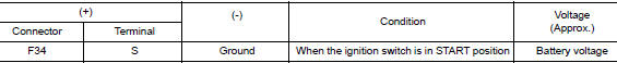
Is the inspection result normal? YES >> “S” circuit is OK. Further inspection is necessary. Refer to STR-11, "Work Flow (With GR8-1200 NI)" or STR-15, "Work Flow (Without GR8-1200 NI)".
NO >> GO TO 2.
2.CHECK HARNESS CONTINUITY (OPEN CIRCUIT)
- Disconnect IPDM E/R connector.
- Check continuity between starter motor harness connector and the IPDM E/R harness connector
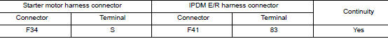
- Check continuity between starter motor terminal S and ground.

Is the inspection result normal? YES >> Further inspection is necessary. Refer to STR-11, "Work Flow (With GR8-1200 NI)" or STR-15, "Work Flow (Without GR8-1200 NI)".
NO >> Repair or replace the harness or connectors.
Symptom diagnosis
STARTING SYSTEM
Symptom Table
| Symptom | Reference |
| No normal cranking | Refer to STR-11, "Work Flow (With GR8-1200 NI)" or STR-15, "Work Flow (Without GR8-1200 NI)". |
| Starter motor does not rotate |
 B terminal circuit
Description
Terminal “B” is constantly supplied with battery power.
Diagnosis Procedure
Regarding Wiring Diagram information, refer to STR-7, "Wiring Diagram".
CAUTION:
Perform diag ...
 Removal and installation
STARTER MOTOR
Exploded View
REMOVAL
Transaxle assembly
Starter motor
Lower bolt
Upper bolt
Removal and Installation
REMOVAL
Remove battery tray. Refer to PG-77, & ...
Other materials:
Glove box lamp
Bulb Replacement
WARNING:
Do not touch the glass surface of a bulb while it is lit or right after being
turned OFF to prevent burns.
CAUTION:
Do not touch the glass of bulb directly by hand. Keep grease
and other oily substances away from
bulb surface.
Do not leave bulb ...
Component parts
METER SYSTEM
METER SYSTEM : Component Parts Location
Vehicle front
View of the fuel pump and fuel level
sensor inspection hole covers with
the rear seat removed.
View of front engine assembly
No.
Component
Function
1
Combination me ...
Wind deflector
Removal and Installation
REMOVAL
Remove headlining Refer to INT-30, "Removal and Installation".
Open the glass lid to view the wind deflector.
Use suitable tool (A) release pawl on LH/RH side of wind deflector.
: Pawl
Release wind deflector retainer (1) ...
