Nissan Rogue Service Manual: B terminal circuit
Description
Terminal “B” is constantly supplied with battery power.
Diagnosis Procedure
Regarding Wiring Diagram information, refer to STR-7, "Wiring Diagram".
CAUTION: Perform diagnosis under the condition that the engine cannot start by the following procedure.
- Remove fuel pump fuse.
- Crank or start the engine (where possible) until the fuel pressure is released.
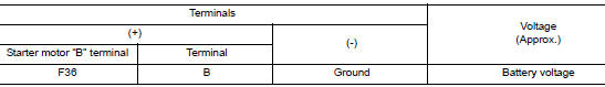
1.CHECK “B” TERMINAL CIRCUIT
- Turn ignition switch OFF.
- Check that starter motor ”B” terminal connection is clean and tight.
- Check voltage between starter motor ”B” terminal and ground.
Is the inspection result normal? YES >> GO TO 2.
NO >> Check harness between battery and starter motor for open circuit.
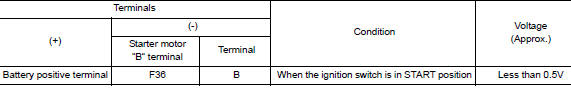
2.CHECK BATTERY CABLE CONNECTION STATUS (VOLTAGE DROP TEST)
- Shift selector lever to ”P” (Park) or ”N” (Neutral) position.
- Check voltage between battery positive terminal and starter motor ”B” terminal.
Is the inspection result normal? YES >> GO TO 3.
NO >> Check harness between the battery and starter motor for continuity.
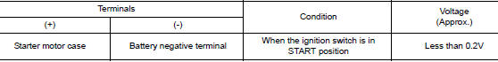
3.CHECK GROUND CIRCUIT STATUS (VOLTAGE DROP TEST)
- Shift selector lever to ”P” (Park) or ”N” (Neutral) position.
- Check voltage between starter motor case and battery negative terminal.
Is the inspection result normal?
YES >> “B” terminal circuit is OK. Further inspection is necessary. Refer to STR-11, "Work Flow (With GR8-1200 NI)" or STR-15, "Work Flow (Without GR8-1200 NI)".
NO >> Check the starter motor case to engine mounting for high resistance.

 S connector circuit
Description
The starter motor magnetic switch is supplied with power when the ignition
switch is turned to the START position
while the selector lever is in the P (Park) or N (Neutral) position.
...
Other materials:
Symptom diagnosis
POWER DOOR LOCK SYSTEM SYMPTOMS
Symptom Table
DOOR LOCK/UNLOCK FUNCTION MALFUNCTION
NOTE:
Before performing the diagnosis in the following table, check
“WORK FLOW”. Refer to DLK-312, "Work
Flow".
Check that vehicle is under the condition shown in “Conditions ...
B142A ignition voltage
Description
DTC B142A IGNITION VOLTAGE
Ignition voltage is supplied to the air bag diagnosis sensor unit when the
ignition is in the ON position. The air
bag diagnosis sensor unit will monitor for low or high ignition voltage.
PART LOCATION
Refer to SRC-6, "Component Parts Location" ...
Unit disassembly and assembly
REAR DRIVE SHAFT
Exploded View
DISASSEMBLY
Circular clip
Dust shield
Slide joint housing
Snap ring
Spider assembly
Boot band
Boot
Shaft
Circular clip
Joint sub-assembly
Sensor rotor
: Wheel side
Disassembly and Assembly
DISASSEMBLY
Final Dri ...
