Nissan Rogue Service Manual: Removal and installation
AV CONTROL UNIT
Exploded View
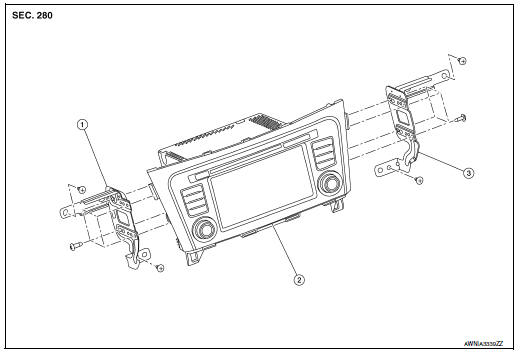
- AV control unit bracket (LH)
- AV control unit
- AV control unit bracket (RH)
Removal and Installation
REMOVAL
CAUTION:
- Before disconnecting the AV control unit and battery terminals, turn the ignition switch OFF and wait at least 30 seconds.
- Before replacing AV control unit, perform “READ CONFIGURATION” to save current vehicle specification.
Refer to AV-134, "CONFIGURATION (AV CONTROL UNIT) : Configuration List".
NOTE: After the ignition switch is turned OFF, the AV control unit continues operating for approximately 30 seconds.
Therefore, data corruption may occur if battery voltage is cut off within 30 seconds.
- Disconnect the negative battery terminal. Refer to PG-75, "Removal and Installation (Battery)".
- Remove A/C switch. Refer to HAC-102, "Removal and Installation".
- Remove instrument finisher B. Refer to IP-16, "INSTRUMENT FINISHER B : Removal and Installation".
- Remove instrument finisher E. Refer to IP-16, "INSTRUMENT FINISHER E : Removal and Installation".
- Remove the AV control unit screws, then pull out the AV control unit.
- Disconnect the harness connectors from the AV control unit and remove.
- Remove the AV control unit bracket (LH/RH) screws and the AV control unit brackets (LH/RH) (if necessary).
INSTALLATION
Installation is in the reverse order of removal.
CAUTION:When replacing AV control unit, perform “WRITE CONFIGURATION”. Refer to AV-134, "CONFIGURATION (AV CONTROL UNIT) : Configuration List".
STEERING SWITCH
Exploded View
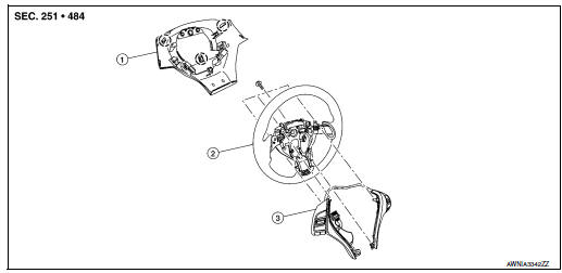
- Steering wheel rear finisher
- Steering wheel
- Steering switches
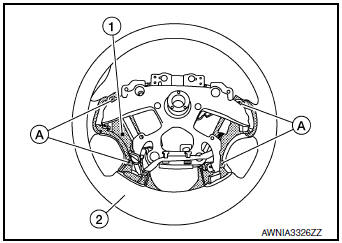
 Pawl
Pawl
Removal and Installation
REMOVAL
NOTE: The steering switches are serviced as an assembly.
- Remove steering wheel. Refer to ST-11, "Removal and Installation".
- Release pawls on the steering wheel rear finisher and remove.
- Remove screws (A) and steering switches (1) from steering wheel (2).
INSTALLATION
Installation is in the reverse order of removal.
BOSE SPEAKER AMP
Removal and Installation
REMOVAL
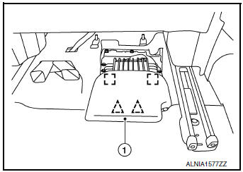
- Slide the passenger seat to the full forward position.
- Release the clips using a suitable tool and remove Bose
speaker amp cover (1).
 : Metal clip
 : Clip
- Remove Bose speaker amp bolts (A).
- Disconnect the harness connectors (B) from the Bose speaker amp (1).
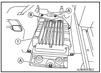
- Remove the Bose speaker amp. and bracket as an assembly.
- Remove the bolts and the Bose speaker amp. from the Bose speaker amp. bracket (if necessary).
INSTALLATION
Installation is in the reverse order of removal.
FRONT TWEETER
Removal and Installation
REMOVAL
- Remove defroster grille. Refer to VTL-12, "DEFROSTER GRILLE : Removal and Installation".
- Remove bolts and pull out the front tweeter.
- Disconnect the harness connector from the front tweeter and remove.
INSTALLATION
Installation is in the reverse order of removal.
FRONT DOOR SPEAKER
Exploded View
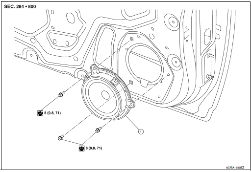
- Front door speaker
Removal and Installation
REMOVAL
- Remove front door finisher. Refer to INT-15, "Removal and Installation".
- Remove front door speaker bolts, then pull out front door speaker.
- Disconnect the harness connector from front door speaker and remove.
INSTALLATION
Installation is in the reverse order of removal.
CENTER SPEAKER
Removal and Installation
REMOVAL
- Release the metal clips (A) using a suitable tool and remove center speaker grille (1).
- Remove the center speaker bolts (B).
- Pull out the center speaker (2).
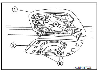
- Disconnect the harness connector from the center speaker and remove.
INSTALLATION
Installation is in the reverse order of removal.
REAR DOOR SPEAKER
Exploded View
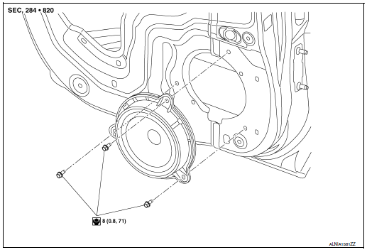
- Rear door speaker
Removal and Installation
REMOVAL
- Remove rear door finisher. Refer to INT-18, "Removal and Installation".
- Remove rear door speaker bolts, then pull out rear door speaker.
- Disconnect the harness connector from the rear door speaker and remove.
INSTALLATION
Installation is in the reverse order of removal.
SUBWOOFER
Removal and Installation
REMOVAL
- Open the rear luggage floor finisher (1).
- Remove the spare tire clamp (3) by rotating counterclockwise.
- Disconnect the harness connector (A) from the subwoofer (2)
and remove.
 : Front
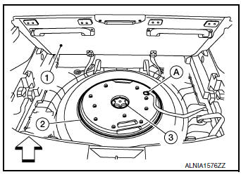
INSTALLATION
Installation is in the reverse order of removal.
USB INTERFACE AND AUX IN JACK
Removal and Installation
REMOVAL
- Remove cluster lid C. Refer to IP-21, "Removal and Installation".
- Release the pawls (A) on the back of USB interface and AUX in jack (2), then remove from the front of cluster lid C (1).
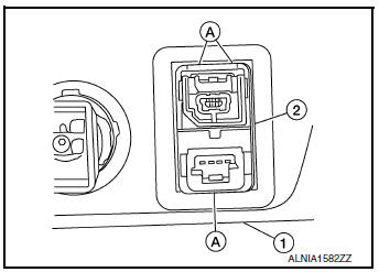
INSTALLATION
Installation is in the reverse order of removal.
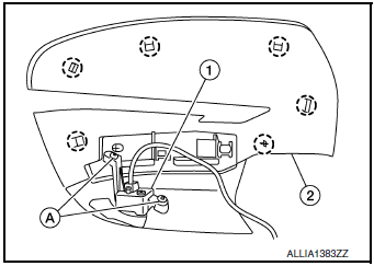
MICROPHONE
Removal and Installation
REMOVAL
- Remove the map lamp assembly. Refer to INL-55, "Removal and Installation".
- Release harness connector (A) by sliding rearward to remove from the pawl (B).
- Release pawls (C) and remove the microphone (1) from the front room/map lamp assembly.
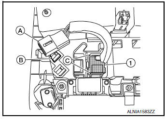
INSTALLATION
Installation is in the reverse order of removal.
AROUND VIEW MONITOR CONTROL UNIT
Exploded View
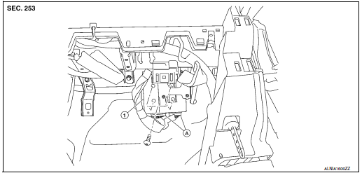
- Around view monitor control unit
- Harness connector
Removal and Installation
REMOVAL
CAUTION: Before replacing around view monitor control unit, save or print current vehicle specification with CONSULT configuration before replacement. Refer to AV-288, "ADDITIONAL SERVICE WHEN REPLACING AROUND VIEW MONITOR CONTROL UNIT : Work Procedure".
- Remove glove box assembly. Refer to IP-23, "Removal and Installation".
- Remove around view monitor control unit screws.
- Disconnect the harness connector from the around view monitor control unit and remove.
INSTALLATION
Installation is in the reverse order of removal.
CAUTION:
- Replace the around view monitor control unit if it has been dropped or sustained an impact.
- When replacing around view monitor control unit, you must
perform "After Replace ECU" with CONSULT.
Refer to AV-288, "ADDITIONAL SERVICE WHEN REPLACING AROUND VIEW MONITOR CONTROL UNIT : Work Procedure".
NOTE: Perform camera image calibration. Refer to AV-292, "CALIBRATING CAMERA IMAGE (AROUND VIEW MONITOR) : Work Procedure".
FRONT CAMERA
Exploded View
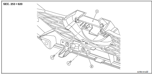
- Front grille
- Front camera
Removal and Installation
REMOVAL
- Remove the front grille. Refer to EXT-23, "Removal and Installation".
- Remove screws and front camera.
INSTALLATION
Installation is in the reverse order of removal.
NOTE: Perform camera image calibration. Refer to AV-292, "CALIBRATING CAMERA IMAGE (AROUND VIEW MONITOR) : Work Procedure".
SIDE CAMERA
Removal and Installation
REMOVAL
- Remove door mirror rear finisher (2). Refer to MIR-25, "Removal and Installation".
- Remove screws (A) and side camera (1).
 : Pawl
INSTALLATION
Installation is in the reverse order of removal.
CAUTION: Perform camera image calibration (if equipped with around view camera). Refer to AV-135, "CALIBRATING CAMERA IMAGE (AROUND VIEW MONITOR) : Description".
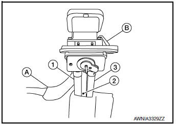
REAR VIEW CAMERA
Removal and Installation
REMOVAL
- Remove the back door outer finisher. Refer to EXT-50, "Removal and Installation".
- Disconnect washer tubes (1,3) and air tube (2) (if equipped).
- Release pawl (B), disconnect harness connector (A) from rear view camera and remove.
INSTALLATION
Installation is in the reverse order of removal.
GPS ANTENNA
Removal and Installation
REMOVAL
- Remove instrument panel. Refer to IP-14, "INSTRUMENT PANEL ASSEMBLY : Removal and Installation".
- Remove screw and the GPS antenna.
INSTALLATION
Installation is in the reverse order of removal.
AUDIO ANTENNA
Removal and Installation
REMOVAL
- Remove the luggage side upper finisher (RH). Refer to INT-36, "LUGGAGE SIDE UPPER FINISHER : Removal and Installation".
- Partially lower headlining (rear). Refer to INT-30, "Removal and Installation".
- Disconnect harness connectors from antenna feeder.
- Remove nut from audio antenna and remove.
INSTALLATION
Installation is in the reverse order of removal.
Audio antenna nut : 6.5 N·m (0.66 kg-m, 58 in-lb)
CAUTION: If the audio antenna nut is not properly tightened, lower sensitivity of the antenna may be experienced.
If the nut is over tightened, this will deform the roof panel.
ANTENNA FEEDER
Feeder Layout
ANTENNA FEEDER LAYOUT
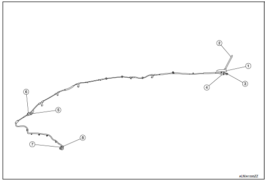
- Antenna base (antenna amp. and satellite antenna)
- Rod Antenna
- M503
- M502
- M130, M501
- M129, M500
- M142
- M139
 Symptom diagnosis
MULTI AV SYSTEM
Symptom Table
RELATED TO AUDIO
RELATED TO HANDS-FREE PHONE
Before performing diagnosis, confirm that the cellular phone being
used by the customer is co ...
 Cruise control
...
Other materials:
Instrument panel
Vent
Headlight/fog light (if so equipped)/turn signal switch
Meters, gauges, warning/indicator
lights and Vehicle Information Display
Windshield wiper/washer switch and rear window wiper/washer switch
/Ignition switch (if so equipped)
Push-button ...
System description
COMPONENT PARTS
POWER DOOR LOCK SYSTEM
POWER DOOR LOCK SYSTEM : Component Parts Location
No
Component
Function
1
BCM
Controls the door lock system.
Refer to BCS-7, "BODY CONTROL SYSTEM : Component Parts Location" for
detailed
install ...
P0116 ECT sensor
DTC Description
DTC DETECTION LOGIC
DTC No.
CONSULT screen terms
(Trouble diagnosis content)
DTC detecting condition
P0116
ECT SENSOR
(Engine coolant temperature sensor 1 circuit
range/performance)
The comparison result of signals transmitted to ECM from each
...
