
Nissan Rogue (T33) 2021-Present Service Manual: Preparation
Special Service Tool
The actual shape of the tools may differ from those illustrated here.
|
Tool number (TechMate No.) Tool name | Description | |
|---|---|---|
|
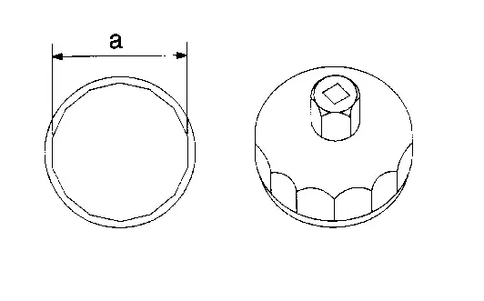
KV10115801 (NI-38956) Oil filter wrench |
|
Removing and installing oil filter a: 64.3 mm (2.531 in) |
|
|
CVT fluid changing and adjustment |
|
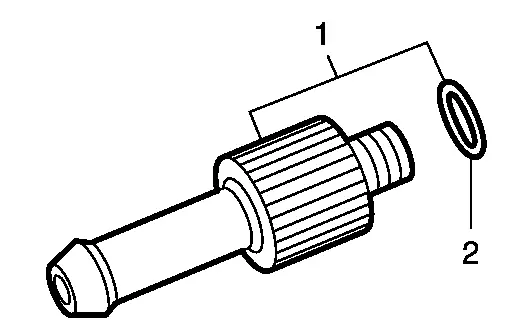
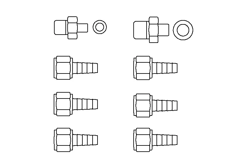
— (NI-52584) CVT stand pipe adapter kit |
|
CVT fluid changing and adjustment |
|
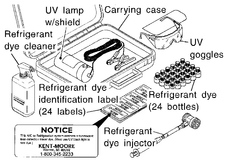
— (NI-43926) Refrigerant dye leak detection kit Kit includes: UV lamp and UV safety goggles Refrigerant dye injector Fluorescent leak detection dye (box of 24, 1/4 ounce bottles) Refrigerant dye cleaner |
|
Oil seepage and leak inspection
Power supply: DC 12V (battery terminal) |
|
— (NI-52990) Fluorescent Oil Dye |
|
Oil seepage and leak inspection |
|
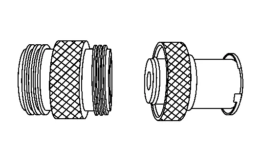
— (NI-52611) CVT charge pipe cap release tool |
|
Removing CVT charge pipe cap |
|
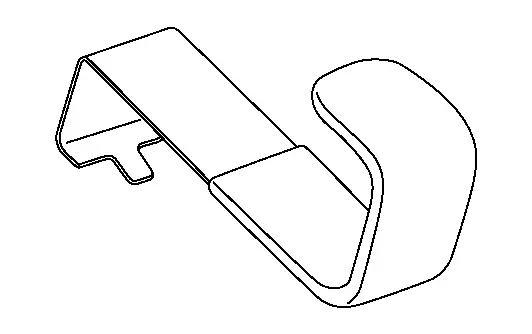
EG17651130 ( — ) Radiator cap tester adapter |
|
|
|
KV991J0070 (NI-45695-A) Coolant refill tool |
|
Refilling engine cooling system |
|
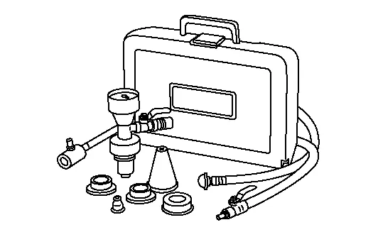
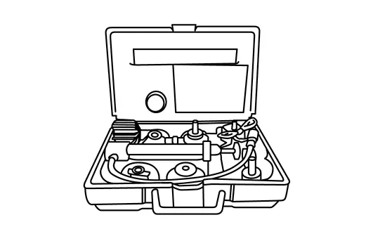
 — (NI-51771) Cooling system pressure test kit
|
|
Checking cooling system |
 NOTE:
NOTE:
*: The O-ring as a unit part is set as a SST.
Commercial Service Tool
| Tool name | Description | |
|---|---|---|
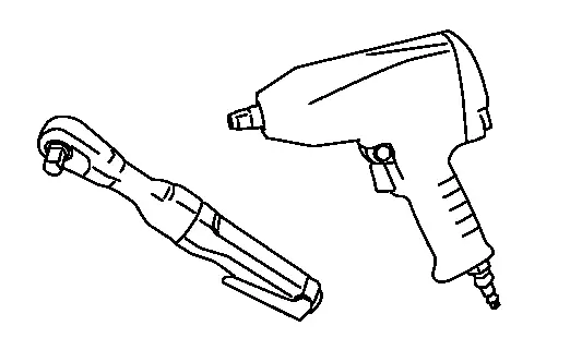
| Power tool |
|
Loosening nuts and bolts |
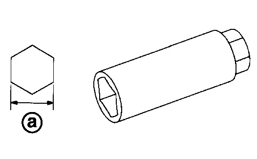
| Spark plug wrench |
|
Removing and installing spark plug a: 14 mm (0.55 in) |
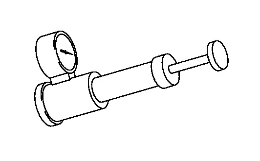
| Radiator cap tester |
|
Checking radiator and radiator cap |
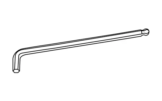
| Ball point hex wrench |
|
Removing and installing oil drain plug. |
Always Replace with New Parts
| Never Reuse These Parts | Part Code | For additional information |
|---|---|---|
| Washer-drain plug | 11128A | Exploded View |
| Plug-drain | 11128 | Exploded View |
| O-ring | — | Exploded View |
| Gasket | 33100Q | Exploded View |
| Gasket - drain plug | 38351W | Exploded View |
Other materials:
P2122 App Sensor
DTC Description
DTC DETECTION LOGIC DTC
CONSULT screen terms
(Trouble diagnosis content)
DTC detection condition
P2122
00
APP SEN 1/CIRC
(Throttle/Pedal position sensor/switch D circuit low)
Diagnosis condition
Engine running at idle
Signal (terminal)
Accelerator ...
Automatic Emergency Braking. Ecu Diagnosis Information
Adas Control Unit 2
List of ECU Reference
ECU Reference
ADAS control unit 2 (Without ProPILOT Assist 2.1)
Reference Value
Fail-safe (ADAS Control Unit 2)
DTC Inspection Priority Chart
DTC Index
ADAS control unit 2 (With ProPILOT Assist 2.1)
Reference Value
Fail- ...
Motion-activated liftgate
Basic information
The Nissan Rogue liftgate can be opened using a quick forward kicking motion beneath the center area of the rear bumper.
The kick motion sensor a is located behind the bumper. When your foot moves under and away from the detection area b while carrying the Intelligent Key, ...