Nissan Rogue (T33) 2021-Present Service Manual: Power Distribution System :: System Description
Component Parts
Component Parts Location

 : Front of vehicle
| A. | Relay box | B. | Fuse block (J/B)[view with fuse block (J/B) removed] |
| No. | Component | Function |
|---|---|---|
| 1. | IPDM E/R (Intelligent Power Distribution Module Engine Room) |
Receives ignition relay (IPDM E/R) control signal and push-button ignition switch ON signal from the Intelligent Key unit via CAN communication, and controls the ignition relay (built into IPDM E/R). Refer to System Description. |
| 2. | Combination switch (lighting and turn signal switch) |
Transmits the combination switch signal to the BCM. Refer to System Description. |
| 3. | TCM (Transmission Control Module) |
Transmits the P (park) and N (neutral) signals to the BCM via CAN communication. Refer to TCM for detailed component location. |
| 4. | BCM (Body Control Module) |
|
| 5. | Stop lamp switch |
Transmits the stop lamp switch signal to the BCM. Refer to Stop Lamp Switch for detailed component location. |
| 6. | Front power window motor (driver side) |
Transmits the front power window open/close signal to the BCM via LIN communication. Refer to Front Power Window Motor (Driver Side) for detailed component location. |
| 7. | Door lock assembly (door switch) |
Transmits the door switch signal to the BCM. Refer to Door Lock Assembly for detailed component location. |
| 8. | Back door opener switch (request switch) |
Transmits the request switch signal to the Intelligent Key unit. Refer to Back Door Opener Switch for detailed component location. |
| 9. | Back door lock assembly (ajar switch) |
Transmits the ajar switch signal to the BCM. Refer to Back Door Lock Assembly for detailed component location. |
| 10. | Front door request switch |
Transmits the request switch signal to the Intelligent Key unit. Refer to Door Request Switch for detailed component location. |
| 11. | Push-button ignition switch | Refer to Push-button Ignition Switch. |
| 12. | Intelligent Key unit |
Receives the push-button switch signal and transmits it to the BCM and IPDM E/R via CAN communication. Refer to Intelligent Key Unit for detailed component location. |
| 13. | TCU (Telematics Communication Unit) (if so equipped) |
Transmits the auto ACC request signal to the BCM via CAN communication. Refer to TCU for detailed component location. |
| 14. | ABS (Anti-lock Braking System) actuator and electric unit (control unit) |
Transmits the Nissan Ariya vehicle speed signal to the BCM via CAN communication. Refer to ABS Actuator and Electric Unit (Control Unit) for detailed component location. |
| 15. | Ignition relay-3 |
|
| 16. | Ignition relay-2 [in fuse block (J/B)] |
|
| 17. | Ignition relay-1 [in fuse block (J/B)] |
|
| 18. | Accessory relay [in fuse block (J/B)] |
|
Push-Button Ignition Switch
-
The push-button ignition switch is installed in the front of the center console.

-
When the push-button ignition switch is pressed it transmits the status signal to the Intelligent Key unit.
System
Power Distribution System
System Description
SYSTEM DIAGRAM
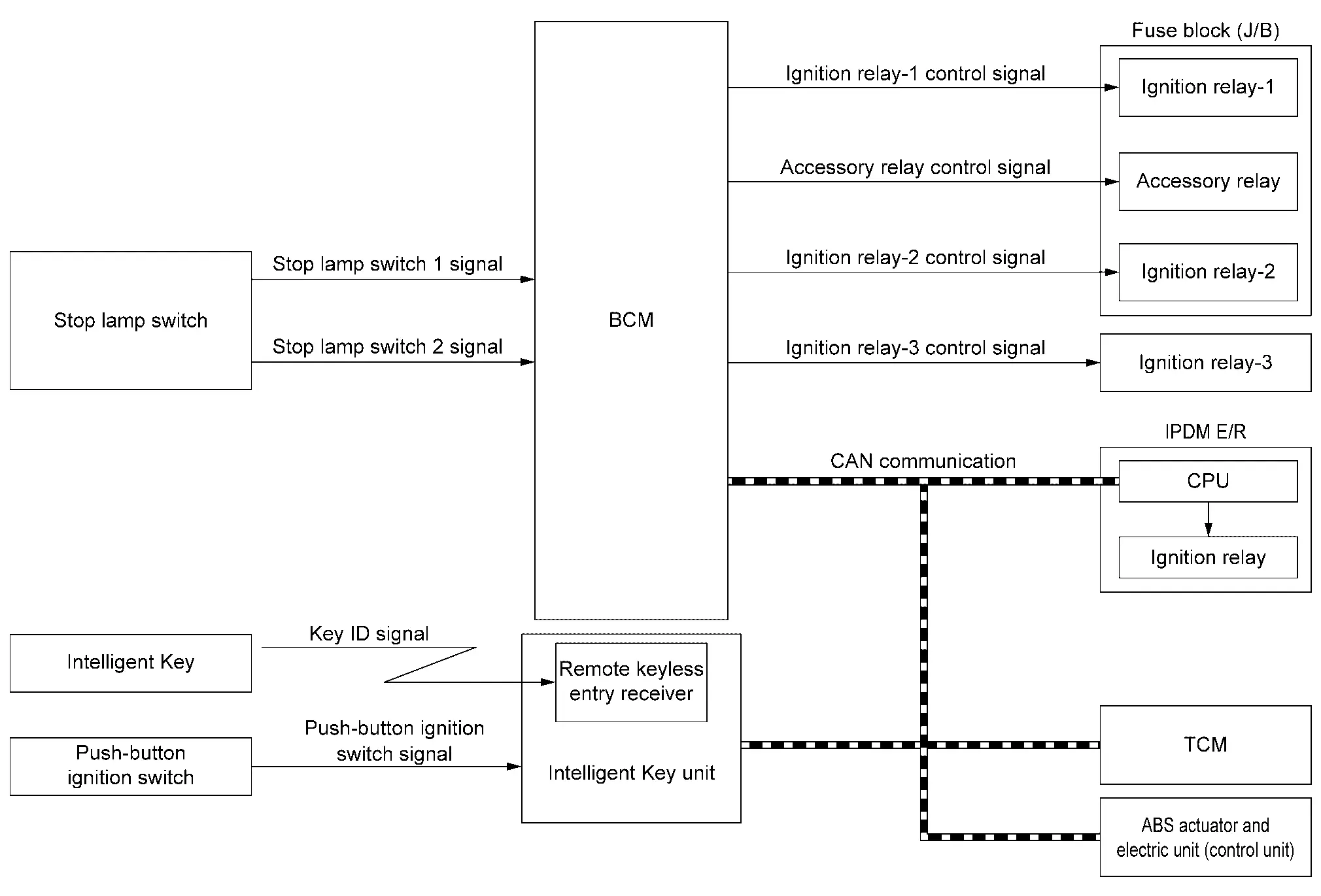
| Component | Function |
|---|---|
| Intelligent Key | Operates based on the results of electronic ID verification using two-way communication between the Intelligent Key and the Nissan Ariya vehicle (Intelligent Key unit). |
| Push-button ignition switch | Refer to Push-button Ignition Switch. |
| Stop lamp switch | Stop lamp switch detects that brake pedal is depressed, and then transmits ON/OFF signal to BCM. |
| TCM | Transmits shift position signal and cranking enable signal to BCM via CAN communication. |
| Intelligent Key unit | Transmits push-button ignition switch status signal to BCM via CAN communication. |
| ABS actuator and electric unit (control unit) | Transmits Nissan Ariya vehicle speed signal to BCM via CAN communication. |
| BCM |
|
| Ignition relay-1 [fuse block (J/B)] | Controlled by BCM and turns ON/OFF the battery power supply to each parts. |
| Accessory relay [fuse block (J/B)] | |
| Ignition relay-2 [fuse block (J/B)] | |
| Ignition relay-3 [fuse block (J/B)] | |
| Ignition relay (IPDM E/R) | Controlled by IPDM E/R and turns ON/OFF the battery power supply to each parts. |
| IPDM E/R | IPDM E/R controls the integrated ignition relay, and supplies voltage to the load according to the request from BCM via CAN communication. |
SIGNAL TRANSMISSION FUNCTION LIST
| Signal name | Input | Output | Description |
|---|---|---|---|
| Stop lamp switch 1 signal | Stop lamp switch | BCM | Transmits the stop lamp switch 1 signal to the BCM. |
| Stop lamp switch 2 signal | Stop lamp switch | BCM | Transmits the stop lamp switch 1 signal to the BCM. |
| Push-button ignition switch signal | Push-button ignition switch | Intelligent Key unit | Transmits the push-button ignition switch signal to the Intelligent Key unit. |
| P/N position signal | TCM | BCM (CAN) | Transmits the P/N position signal via CAN communication. |
| Shift position signal | TCM | BCM (CAN) | Transmits the shift position signal via CAN communication. |
| Cranking enable signal | TCM | BCM (CAN) |
Transmits the cranking enable signal via CAN communication. |
| Remote engine start signal | Intelligent Key unit | BCM (CAN) |
Transmits the remote engine start signal via CAN communication. |
| Push-button ignition switch status signal | Intelligent Key unit | BCM (CAN) | Transmits the push-button ignition switch status signal via CAN communication. |
| Nissan Ariya Vehicle speed signal | ABS actuator and electric unit (control unit) | BCM (CAN) | Transmits the Nissan Ariya vehicle speed signal via CAN communication. |
| Push-button ignition switch ON signal | BCM | IPDM E/R (CAN) | Transmits the push-button ignition switch ON signal via CAN communication. |
SYSTEM DESCRIPTION
-
POWER DISTRIBUTION SYSTEM is the system that BCM controls with the operation of push-button ignition switch and performs the power distribution to each power circuit. This system is used instead of the mechanical power supply changing mechanism with the operation of the conventional key cylinder.
Allocation to the accessory power supply, refer to the auto ACC function. Refer to System Description.
-
Push-button ignition switch can be operated when Intelligent Key is in the following condition:
-
Intelligent Key is in the detection area of the inside key antenna.
-
Intelligent Key backside is contacted to push-button ignition switch.
-
-
Push-button ignition switch operation is input to Intelligent Key unit as a signal. Intelligent Key unit transmits push-button ignition switch status signal to BCM via CAN communication. BCM changes the ignition switch position according to the status and operates the following relays to supply power to each power circuit:
-
Ignition relay (IPDM E/R)
-
Ignition relay-1 [fuse block (J/B)]
-
Ignition relay-2 [fuse block (J/B)]
-
Ignition relay-3 (relay box)
 NOTE:
NOTE:
Ignition relay-3 turns ON only when the engine is running.
-
Accessory relay [fuse block (J/B)]
-
IGNITION BATTERY SAVER SYSTEM
Ignition battery saver system is a system in which the BCM automatically shuts off the power supply (ignition switch ON -> OFF) to protect the battery.
BCM activates ignition battery saver system 10 minutes after ignition battery saver timer function operating conditions are met.
Operating Condition of Ignition Battery Saver Timer Function
When all the following conditions are met for a 10 minutes, the battery saver system will cut off the power supply (ignition switch ON -> OFF) to prevent battery discharge:
-
Ignition switch is in the ON
-
Engine stopped
Cancel Condition of Ignition Battery Saver Timer Function
If any of the following conditions are met the battery saver timer function is canceled:
-
Ignition switch is not ON
-
Engine running
NOTE:
-
Ignition battery saver timer function will return 1 minute or more, after closing CONSULT or removing VI from the Nissan Ariya vehicle.
-
When ignition battery saver is disabling, the operation of push-button ignition switch less than 2 seconds is not accepted.
-
To resume ignition battery saver system, press and hold the push-button ignition switch continuously for 3 seconds or more with the brake pedal is not depressed (ignition switch ON -> OFF).
IGNITION SWITCH POSITION CHANGE TABLE BY PUSH-BUTTON IGNITION SWITCH OPERATION
Refer to System Description.
Auto Acc Function
System Description
SYSTEM DIAGRAM
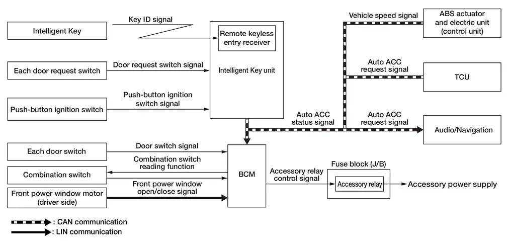
| Component | Function |
|---|---|
| Intelligent Key | Operates based on the results of electronic ID verification using two-way communication between the Intelligent Key and the Nissan Ariya vehicle (Intelligent Key unit). |
| Door request switch | Detects door lock/unlock operation. |
| Push-button ignition switch | Refer to Push-button Ignition Switch. |
| Door switch | Detects door open/close condition. |
| Combination switch (lighting and turn signal switch) | Transmits each switch condition signal to the BCM. |
| Front power window motor (driver side) | Transmits the front power window open/close signal to the BCM via LIN communication. |
| Intelligent Key unit | Transmits the push-button ignition switch status signal and door lock/unlock request signal to the BCM via CAN communication. |
| ABS actuator and electric unit (control unit) | Transmits Nissan Ariya vehicle speed signal to the BCM via CAN communication. |
| TCU | Transmits the auto ACC request signal to the BCM via CAN communication. |
| BCM | BCM operates the auto ACC function based on each signal state. |
| Accessory relay | Controlled by the BCM and turns ON/OFF the battery power supply to each switch and unit. |
| Audio/Navigation |
|
SIGNAL TRANSMISSION FUNCTION LIST
| Signal name | Input | Output | Description |
|---|---|---|---|
| Door request switch signal | Each door request switch | Intelligent Key unit | Transmits the door request switch signal to the Intelligent Key unit. |
| Push-button ignition switch signal | Push-button ignition switch | Intelligent Key unit | Transmits the push-button ignition switch signal to the Intelligent Key unit. |
| Door switch signal | Each door switch | BCM | Transmits the door switch signal to the BCM. |
| Combination switch signal | Combination switch | BCM | Transmits the combination switch signal to the BCM. |
| Front power window open/close signal | Front power window motor (driver side) | BCM (LIN) | Transmits the front power window open/close signal via LIN communication. |
| Nissan Ariya Vehicle speed signal | ABS actuator and electric unit (control unit) | BCM (CAN) | Transmits the Nissan Ariya vehicle speed signal via CAN communication. |
| Auto ACC request signal |
|
BCM (CAN) | Transmits the auto ACC request signal via CAN communication. |
| Auto ACC status signal | BCM |
|
Transmits the auto ACC status signal via CAN communication. |
DESCRIPTION
In conventional vehicles, power is supplied to the accessories of the vehicle after the ignition switch is placed to ACC.
The AUTO ACC function is a function that bypasses ignition switch ACC and automatically distributes the accessory power supply to each switch and unit by door unlock operation, etc. using the Intelligent Key.
OPERATION FLOW
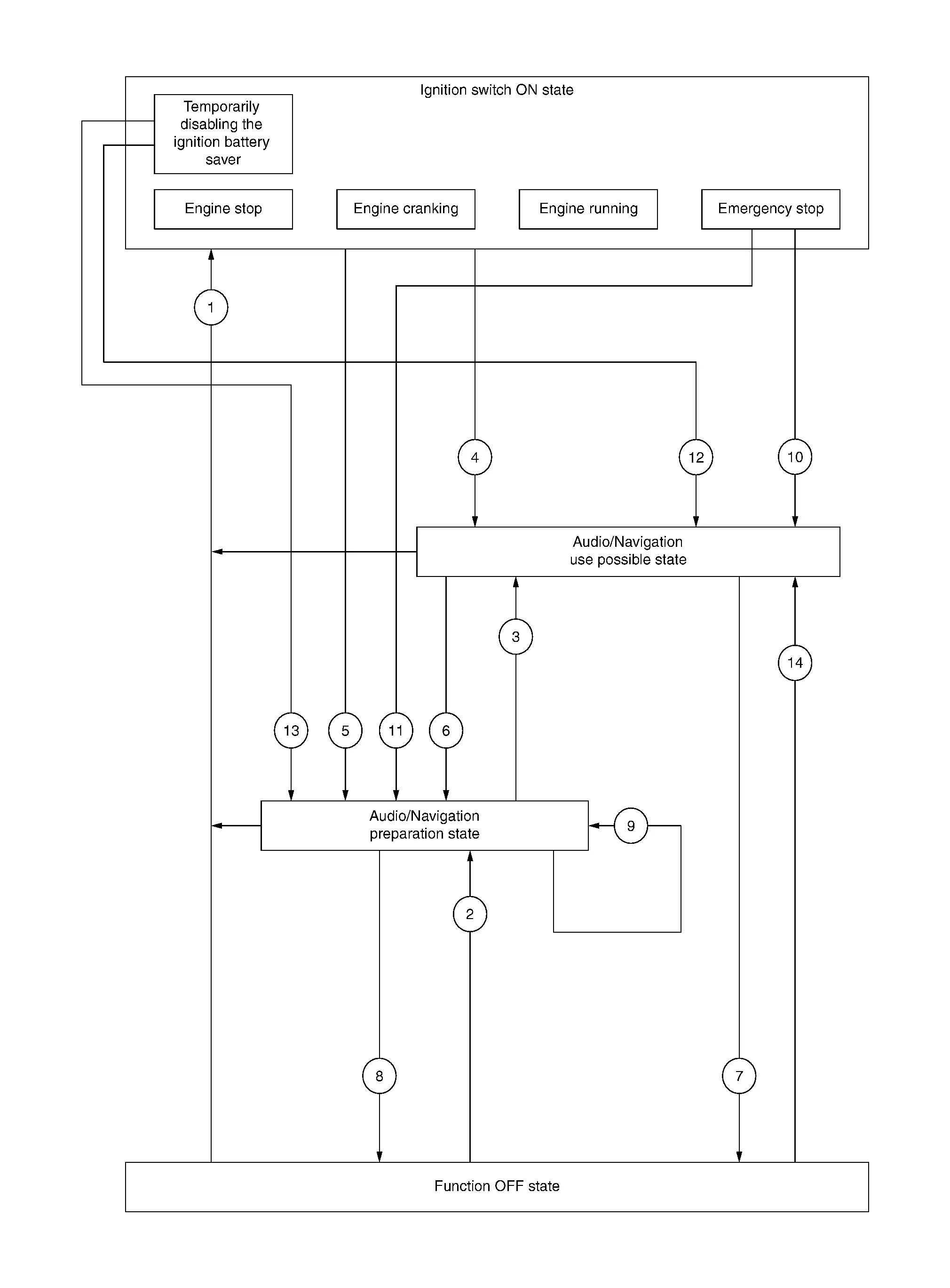
Ignition switch ON state
In this status the ignition switch is operated and placed ON.
Audio/Navigation use possible state
-
In this status the audio/navigation, and each switch and unit that is activated by the accessory power supply can be operated.
-
When 10 minutes pass after conditions are satisfied while and audio/navigation are not operated, audio/navigation turn OFF.
Audio/Navigation preparation state
-
In this status audio/navigation are stopped, but the switches and units other than those for audio/navigation that can operate by using the accessory power supply are available until the accessory power supply turns OFF.
-
When audio/navigation is operated within 1 minutes after conditions are satisfied, operation time is extended for 10 minutes. Audio/navigation can be operated for a maximum of 30 minutes after the status is satisfied.
Function OFF state
In this status the AUTO ACC function stops and power to the accessories is not supplied.
| No. | Function status | Shifting condition | Accessory power supply |
|---|---|---|---|
 |
Shifting from “Function OFF state” to "Ignition switch ON state" |
Any of the following conditions is satisfied:
|
OFF –> ON |
| Shifting from “Audio/Navigation preparation state” to “Ignition switch ON state” | ON | ||
| Shifting from “Audio/Navigation use possible state” to “Ignition switch ON state” | ON | ||
 |
Shifting from “Function OFF state” to “Audio/Navigation preparation state” |
Any of the following conditions is satisfied:
|
OFF –> ON |
 |
Shifting from “Audio/Navigation preparation state” to “Audio/Navigation use possible state” | Operate audio/navigation. | ON |
 |
Shifting from “Ignition switch ON state” to “Audio/Navigation use possible state” | Place the ignition switch OFF from ON while the front door LH is closed. | ON |
 |
Shifting from “Ignition switch ON state” to “Audio/Navigation preparation state” | Place the ignition switch OFF from ON while the front door LH is open. | ON |
 |
Shifting from “Audio/Navigation use possible state” to “Audio/Navigation preparation state” |
Any of the following conditions is satisfied:
|
ON |
 |
Shifting from “Audio/Navigation use possible state” to “Function OFF state” | 30 minutes pass from “Audio/Navigation use possible state”. | ON –> OFF |
 |
Shifting from “Audio/Navigation preparation state” to “Function OFF state” | 1 minute passes from “Audio/Navigation preparation state”. | ON –> OFF |
 |
Shifting from “Audio/Navigation preparation state” time extension (approx. 1 minute) |
Any of the following conditions is satisfied:
|
ON |
 |
Shifting from “Ignition switch ON state” (in status of emergency stop) to “Audio/Navigation use possible state” | Except front door LH is opened. | ON |
 |
Shifting from “Ignition switch ON state” (in status of emergency stop) to “Audio/Navigation preparation state” | Front door LH is opened. | ON |
 |
Shifting from “Ignition switch ON state” (in status of temporarily disabling the ignition battery saver) to “Audio/Navigation use possible state” |
Press and hold the push-button ignition switch continuously for 3 seconds or more when all of the following conditions are satisfied:
|
ON |
 |
Shifting from “Ignition switch ON state” (in status of temporarily disabling the ignition battery save) to “Audio/Navigation preparation state” |
Press and hold the push-button ignition switch continuously for 3 seconds or more when all of the following conditions are satisfied:
|
ON |
 |
Shifting from “Function OFF state” to “Audio/Navigation use possible state” | Operate telematics system. | OFF –> ON |
Diagnosis System (bcm)
Common Item
CONSULT Function (BCM - COMMON ITEM)
| BCM | Refer to CONSULT Function (BCM - COMMON ITEM). |
Diagnosis System (ipdm E/r)
CONSULT Function (IPDM E/R)
| IPDM E/R | Refer to CONSULT Function (IPDM E/R). |
Diagnosis System (intelligent Key Unit)
CONSULT Function (INTELLIGENT KEY)
| Intelligent Key unit | Refer to CONSULT Function (INTELLIGENT KEY). |
Other materials:
Poste de conduite
Cette vue d’ensemble du poste de conduite du Nissan Rogue vous aide à repérer rapidement les commandes essentielles, que vous conduisiez en ville ou sur autoroute. Selon la finition de votre Nissan Rogue, certaines fonctions peuvent être présentes (signalées par *), notamment ProPILOT Assist ...
Plug
Description
Replace the O-ring if oil leaks from the plug.
Exploded View
1.
Plug
2.
O-ring
3.
Plug
4.
O-ring
5.
O-ring
6.
Overflow plug
7.
O-ring
8.
Transaxle assembly
: N·m (kg-m, ft-lb) : N·m (kg-m, in-lb) : Always replace ...
Symptom Diagnosis. Wiper and Washer System Symptoms
Symptom Table (Without Rain and Light Sensor)
NOTE:
Perform the "Self diagnosis result" with CONSULT before
the symptom diagnosis. Perform the trouble diagnosis if any DTC is
detected.
Symptom Possible cause Inspection item
Front wiper does not operate
HI only
BCM
IPDM E ...