Nissan Rogue Service Manual: Parking brake system
Inspection and Adjustment
INSPECTION
Pedal Stroke
- Operate the parking brake pedal with a force of 196 N (20.0 kg-f, 44.1 lb-f). Check that the pedal stroke is within the specified number of notches. (Check it by listening to the clicks of the ratchet.)
Number of notches : Refer to PB-14, "Parking Brake Control".
- When brake warning lamp turns ON, check that the pedal stroke is within
the specified number of notches.
(Check it by listening to the clicks of the ratchet.)
Number of notches : Refer to PB-14, "Parking Brake Control".
Inspect Components
- Check each component for installation condition such as looseness.
- Check the parking brake components for bends, wear, cracks and or damage. Replace if damage is noted.
- Check the parking brake switch, and replace it if necessary. Refer to PB-7, "Exploded View".
ADJUSTMENT
- Secure the disc brake rotor using wheel nuts.
- Remove the instrument lower panel (LH). Refer to IP-22, "Removal and Installation".
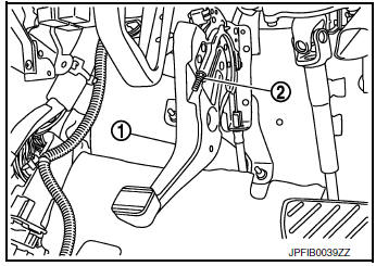
- Release the parking brake pedal (1) by turning the adjusting nut (2) using a suitable tool and loosening the cable.
- Remove the adjusting hole plug from the disc brake rotor. Turn the adjuster (1) in the direction (A) as shown using a suitable tool until the disc rotor is locked.
- Turn back the adjuster 6 - 7 notches from the locked position.
- Rotate the disc brake rotor to check that there is no drag. Install the adjusting hole plug.
- Adjust the cable with the following procedure.
- Operate the parking brake pedal with a force of 490 N (50.0 kg-f, 110.2 lb-f) for more than 30 minutes.
- Adjust the parking brake pedal stroke by turning the adjusting
nut using a suitable tool.
CAUTION: Do not reuse the adjusting nut if the nut is removed.
- Operate the parking brake pedal with a force of 196 N (20.0 kg-f, 44.1 lb-f). Check that the pedal stroke is within the specified number of notches. (Check it by listening to the clicks of the ratchet.)
Number of notches : Refer to PB-14, "Parking Brake Control".
- Rotate the disc brake rotor with the parking brake pedal released and
check that there is no drag.
CAUTION: If any drag is found, verify the parking brake components are installed and adjusted correctly.

 Parking brake shoe
Inspection and Adjustment
Adjust parking brake pedal stroke. Refer to PB-4, "Inspection and
Adjustment".
Perform parking brake break-in (drag on) operation by driving
vehic ...
Other materials:
Power steering
WARNING
If the engine is not running or is turned
off while driving, the power assist for
the steering will not work. Steering will
be harder to operate.
When the power steering warning light
illuminates with the engine running,
there will be no power a ...
DTC/circuit diagnosis
U1000 CAN COMM CIRCUIT
Description
Refer to LAN-8, "System Description".
DTC Logic
DTC DETECTION LOGIC
NOTE:
U1000 can be set if a module harness was disconnected and reconnected, perhaps
during a repair. Confirm
that there are actual CAN diagnostic symptoms and a present DTC by p ...
Satellite radio reception (if so equipped)
When the satellite radio is used for the first time
or the battery has been replaced, the satellite
radio may not work properly. This is not a malfunction.
Wait more than 10 minutes with satellite
radio ON and the vehicle outside of any metal or
large building for satellite radio to receive a ...
