Nissan Rogue (T33) 2021-Present Service Manual: P2a01 Ho2s2
DTC Description
The heated oxygen sensor 2 has a much longer switching time between rich and lean than the air fuel ratio (A/F) sensor 1. The oxygen storage capacity of the three way catalyst (manifold) causes the longer switching time.
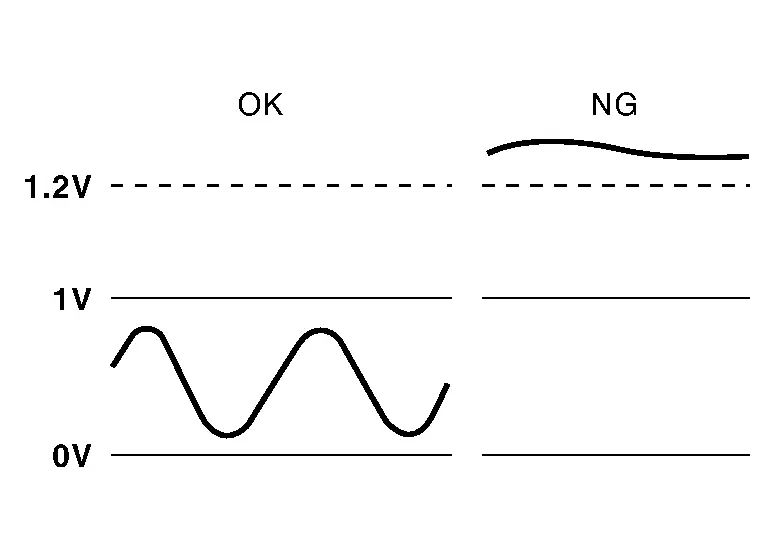
MALFUNCTION A
To judge the malfunctions of heated oxygen sensor 2, ECM monitors whether the voltage is unusually high during various driving conditions such as fuel cut.
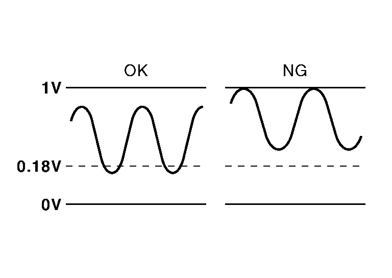
MALFUNCTION B
To judge the malfunctions of heated oxygen sensor 2, ECM monitors whether the minimum voltage is excessively high during various driving conditions such as fuel cut.
DTC DETECTION LOGIC
| DTC |
CONSULT screen terms (Trouble diagnosis content) |
DTC detection condition | |||
| P2A01 | 00 |
O2 sensor bank 1 sensor 2 (O2 Sensor Circuit Range/Performance Bank 1 Sensor 2) |
A | Diagnosis condition | Engine running at fuel cut |
| Signal (terminal) | Heated oxygen sensor 2 signal | ||||
| Threshold | An excessively high voltage from the sensor is sent to ECM | ||||
| Diagnosis delay time | — | ||||
| B | Diagnosis condition | Engine running at fuel cut | |||
| Signal (terminal) | Heated oxygen sensor 2 signal | ||||
| Threshold | The minimum voltage from the sensor is not reached to the specified voltage | ||||
| Diagnosis delay time | — | ||||
POSSIBLE CAUSE
P2A01-A
-
Harness or connectors (The heated oxygen sensor 2 circuit is open or shorted.)
-
Heated oxygen sensor 2
P2A01-B
-
Harness or connectors (The heated oxygen sensor 2 circuit is open or shorted.)
-
Heated oxygen sensor 2
-
Fuel pressure
-
Fuel injector
FAIL-SAFE
Not applicable
DTC Confirmation Procedure
PRECONDITIONING
If DTC Confirmation Procedure has been previously conducted, always perform the following procedure before conducting the next test.
>>
GO TO 2.
DTC CONFIRMATION PROCEDURE FOR MALFUNCTION A
-
Start engine and warm it up to the normal operating temperature.
-
Turn ignition switch OFF and wait at least 10 seconds.
-
Restart engine and keep the engine speed between 3,500 and 4,000 rpm for at least 1 minute under no load.
-
Check 1st trip DTC.
Is 1st trip DTC detected?
YES>>Refer to DTC Diagnosis Procedure.
NO-1>>With CONSULT: GO TO 3.
NO-2>>Without CONSULT: GO TO 5.
DTC CONFIRMATION PROCEDURE FOR MALFUNCTION B-1
 With CONSULT
Test condition: For better results, perform “DTC WORK SUPPORT” at a temperature of 0 to 30°C (32 to 86°F).
-
Turn ignition switch ON and select “DATA MONITOR” mode of “ENGINE” using CONSULT.
-
Start engine and warm it up to the normal operating temperature.
-
Turn ignition switch OFF and wait at least 10 seconds.
-
Restart engine and keep the engine speed between 3,500 and 4,000 rpm for at least 1 minute under no load.
-
Let engine idle for 1 minute.
-
Check that “COOLANT TEMP/S” indicates more than 70°C (158°F).
If not, warm up engine and go to next step when “COOLANT TEMP/S” indication reaches 70°C (158°F).
-
Open engine hood.
-
Select “HO2S2 (B1) P1146” of “HO2S2” in “DTC WORK SUPPORT” mode of “ENGINE” using CONSULT.
-
Follow the instruction of CONSULT display.
 NOTE:
NOTE:
It will take at most 10 minutes until “COMPLETED”is displayed.
-
Touch “SELF-DIAG RESULTS”.
Which is displayed on CONSULT screen?
OK-1>>To check malfunction symptom before repair: Refer to Intermittent Incident.
OK-2>>Confirmation after repair: INSPECTION END
NG>>Refer to DTC Diagnosis Procedure.
CAN NOT BE DIAGNOSED>>GO TO 4.
DTC CONFIRMATION PROCEDURE FOR MALFUNCTION B-2
-
Turn ignition switch OFF and leave the Nissan Ariya vehicle in a cool place (soak the vehicle).
-
Perform DTC confirmation procedure again.
>>
GO TO 3.
PERFORM COMPONENT FUNCTION CHECK
Perform Component Function Check. Refer to Component Function Check.
Is the inspection result normal?
YES-1>>To check malfunction symptom before repair: Refer to Intermittent Incident.
YES-2>>Confirmation after repair: INSPECTION END
NO>>Refer to DTC Diagnosis Procedure.
DTC Diagnosis Procedure
INSPECTION START
Confirm the detected malfunction (A or B). Refer to DTC Description.
Which malfunction is detected?
A>>GO TO 2.
B>>GO TO 7.
CHECK HEATED OXYGEN SENSOR 2 CONNECTOR
-
Disconnect heated oxygen sensor 2 (HO2S2) harness connector.
-
Check that water is not inside connectors.
| There is no leakage. |
Is the inspection result normal?
YES>>GO TO 3.
NO>>Repair or replace malfunctioning part.
CHECK HO2S2 GROUND CIRCUIT
-
Ignition switch OFF.
-
Disconnect ECM harness connector.
-
Disconnect heated oxygen sensor 2 (HO2S2) harness connector.
-
Check the continuity between HO2S2 harness connector and ECM harness connector.
HO2S2 ECM Continuity Connector Terminal Connector Terminal F67 1 F71 97 Existed -
Also check harness for short to ground and short to power.
Is the inspection result normal?
YES>>GO TO 4.
NO>>Repair or replace malfunctioning part.
CHECK HO2S2 INPUT SIGNAL CIRCUIT
-
Check the continuity between HO2S2 harness connector and ECM harness connector.
HO2S2 ECM Continuity Connector Terminal Connector Terminal F67 2 F71 92 Existed -
Check the continuity between HO2S2 harness connector and ground, or ECM harness connector and ground.
HO2S2 — Continuity Connector Terminal F67 2 Ground Not existed ECM — Continuity Connector Terminal F71 92 Ground Not existed -
Also check harness for short to ground and short to power.
Is the inspection result normal?
YES>>GO TO 5.
NO>>Repair or replace malfunctioning part.
CHECK HEATED OXYGEN SENSOR 2
Refer to Component Inspection.
Is the inspection result normal?
YES>>INSPECTION END
NO>>GO TO 6.
REPLACE HEATED OXYGEN SENSOR 2
Replace heated oxygen sensor 2. Refer to Exploded View.
>>
INSPECTION END
PERFORM AIR FUEL RATIO INITIAL LEARNING
-
Start engine and warm it up to the normal operating temperature.
-
Clear the air fuel ratio initial learning. Refer to Work Procedure.
-
Run engine for at least 10 minutes at idle speed.
Is the 1st trip DTC P0172 detected? Is it difficult to start engine?
YES>>Perform trouble diagnosis for DTC P0172. Refer to DTC Description.
NO>>GO TO 8.
CHECK HEATED OXYGEN SENSOR 2 GROUND CIRCUIT
-
Turn ignition switch OFF.
-
Disconnect ECM harness connector.
-
Disconnect heated oxygen sensor 2 (HO2S2) harness connector.
-
Check the continuity between HO2S2 harness connector and ECM harness connector.
HO2S2 ECM Continuity Connector Terminal Connector Terminal F67 1 F71 97 Existed -
Also check harness for short to ground and short to power.
Is the inspection result normal?
YES>>GO TO 9.
NO>>Repair or replace malfunctioning part.
CHECK HO2S2 INPUT SIGNAL CIRCUIT
-
Check the continuity between HO2S2 harness connector and ECM harness connector.
HO2S2 ECM Continuity Connector Terminal Connector Terminal F67 2 F71 92 Existed -
Check the continuity between HO2S2 harness connector and ground, or ECM harness connector and ground.
HO2S2 — Continuity Connector Terminal F67 2 Ground Not existed ECM — Continuity Connector Terminal F71 92 Ground Not existed -
Also check harness for short to ground and short to power.
Is the inspection result normal?
YES>>GO TO 10.
NO>>Repair or replace malfunctioning part.
CHECK HEATED OXYGEN SENSOR 2
Refer to Component Inspection.
Is the inspection result normal?
YES>>INSPECTION END
NO>>GO TO 11.
REPLACE HEATED OXYGEN SENSOR 2
Replace heated oxygen sensor 2. Refer to Exploded View.
>>
INSPECTION END
Other materials:
Dtc/circuit Diagnosis. Front Washer Circuit
Component Function Check
CHECK FRONT WASHER OPERATION
When the front washer switch is turned to the ON position the front washer should operate.
Is front washer operation normal?
YES>>
Washer switch circuit is normal.
NO>>
Refer to Diagnosis Procedure.
Diagnosis Procedure
COMB ...
Ignition Signal
Component Function Check
INSPECTION START
Turn ignition switch OFF, and restart engine.
Does the engine start?
YES-1>>
With CONSULT: GO TO 2.
YES-2>>
Without CONSULT: GO TO 3.
NO>>
Refer to Diagnosis Procedure.
CHECK IGNITION SIGNAL FUNCTION-1
With CONSULT
Perfor ...
System Description. Component Parts. Drive Mode System
Drive Mode System
Component Parts Location
No. Component Function
1.
Drive mode select switch
Refer to Drive Mode Select Switch.
2.
Chassis control module
Chassis control module controls the drive mode select system.
Refer to Component Parts Location (without ProPILOT Assi ...