Nissan Rogue Service Manual: P2138 APP sensor
DTC Description
DTC DETECTION LOGIC
| DTC No. | CONSULT screen terms (Trouble diagnosis content) | DTC detecting condition |
| P2138 | APP SENSOR (Throttle/pedal position sensor/switch ″D″ / ″E″ voltage correlation) | Rationally incorrect voltage is sent to ECM compared with the signals from APP sensor 1 and APP sensor 2. |
POSSIBLE CAUSE
- Harness or connectors (APP sensor 1 or 2 circuit is open or shorted.)
- Accelerator pedal position sensor (APP sensor 1 or 2)
- Sensor power supply 2 circuit
FAIL-SAFE
- The ECM controls the electric throttle control actuator in regulating the throttle opening in order for the idle position to be within +10 degrees.
- The ECM regulates the opening speed of the throttle valve to be slower than the normal condition. So, the acceleration will be poor.
DTC CONFIRMATION PROCEDURE
1.CHECK DTC PRIORITY
If DTC P2138 is displayed with DTC P0643, first perform the trouble diagnosis for DTC P0643.
Is applicable DTC detected? YES >> Perform diagnosis of applicable. Refer to EC-379, "DTC Description".
NO >> GO TO 2.
2.PRECONDITIONING
If DTC Confirmation Procedure has been previously conducted, always perform the following procedure before conducting the next test.
- Turn ignition switch OFF and wait at least 10 seconds.
- Turn ignition switch ON.
- Turn ignition switch OFF and wait at least 10 seconds.
TESTING CONDITION: Before performing the following procedure, confirm that battery voltage is more than 8 V at idle.
>> GO TO 3.
3.PERFORM DTC CONFIRMATION PROCEDURE
- Start engine and let it idle for 1 second.
- Check DTC.
Is DTC detected? YES >> Proceed to EC-449, "Diagnosis Procedure".
NO >> INSPECTION END
Diagnosis Procedure
1.CHECK DTC PRIORITY
If DTC P2138 is displayed with DTC P0643, first perform the trouble diagnosis for DTC P0643.
Is applicable DTC detected? YES >> Perform diagnosis of applicable. Refer to EC-379, "DTC Description".
NO >> GO TO 2.
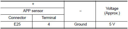
2.CHECK APP SENSOR 1 POWER SUPPLY
- Turn ignition switch OFF.
- Disconnect accelerator pedal position (APP) sensor harness connector.
- Turn ignition switch ON.
- Check the voltage between APP sensor harness connector and ground.
Is the inspection result normal? YES >> GO TO 4.
NO >> GO TO 3.
3.CHECK APP SENSOR 1 POWER SUPPLY CIRCUIT
- Turn ignition switch OFF.
- Disconnect ECM harness connector.
- Check the continuity between APP sensor harness connector and ECM harness connector.
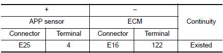
- Also check harness for short to ground.
Is the inspection result normal? YES >> Perform the trouble diagnosis for power supply circuit.
NO >> Repair or replace error-detected parts.
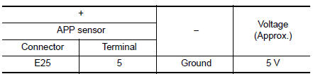
4.CHECK APP SENSOR 2 POWER SUPPLY
Check the voltage between APP sensor harness connector and ground.
Is the inspection result normal? YES >> GO TO 6.
NO >> GO TO 5.
5.CHECK SENSOR POWER SUPPLY 2 CIRCUIT
Perform EC-484, "Diagnosis Procedure".
Is inspection result normal? YES >> Perform the trouble diagnosis for power supply circuit.
NO >> Repair or replace error-detected parts.
6.CHECK APP SENSOR GROUND CIRCUIT
- Turn ignition switch OFF.
- Disconnect ECM harness connector.
- Check the continuity between APP sensor harness connector and ECM harness connector.
- Also check harness for short to power.
Is the inspection result normal? YES >> GO TO 7.
NO >> Repair or replace error-detected parts.
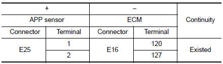
7.CHECK APP SENSOR INPUT SIGNAL CIRCUIT
1. Check the continuity between APP sensor harness connector and ECM harness connector.
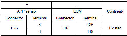
- Also check harness for short to ground and to power.
Is the inspection result normal? YES >> GO TO 8.
NO >> Repair or replace error-detected parts
8.CHECK APP SENSOR
Check the APP sensor. Refer to EC-451, "Component Inspection".
Is the inspection result normal? YES >> GO TO 9.
NO >> Replace accelerator pedal assembly. Refer to ACC-3, "Removal and Installation".
9.CHECK INTERMITTENT INCIDENT
Refer to GI-41, "Intermittent Incident".
>> INSPECTION END
Component Inspection
1.CHECK ACCELERATOR PEDAL POSITION SENSOR
- Turn ignition switch OFF.
- Reconnect all harness connectors disconnected.
- Turn ignition switch ON.
- Check the voltage between ECM harness connector terminals as per the following conditio
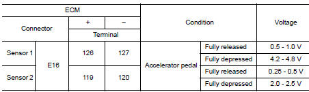
Is the inspection result normal?
YES >> INSPECTION END
NO >> Replace accelerator pedal assembly. Refer to ACC-3, "Removal and Installation".
 P2135 TP sensor
DTC Description
DTC DETECTION LOGIC
DTC No.
CONSULT screen terms
(Trouble diagnosis content)
DTC detecting condition
P2135
TP SENSOR-B1
(Throttle/pedal position sensor ...
 P2610 ECM internal timer
Description
This ECM contains a timer and measures time between an ignition switch OFF
and the next ignition switch
ON. This enables the judging of the state of engine cooling at an engine start.
...
Other materials:
Steering wheel switch for audio control
SOURCE select switch
With the ignition switch in the ACC or ON position,
push the SOURCE switch to turn the audio
system on.
Push the source select switch to change the
mode in the following sequence:
AM→FM1→FM2→SXM1 (satellite radio, if so
equipped) → SXM2 (satellite radio, if so e ...
P0131 A/F sensor 1
DTC Description
DTC DETECTION LOGIC
To judge the malfunction, the diagnosis checks that the A/F signal computed
by ECM from the A/F sensor 1
signal is not inordinately low.
DTC No.
CONSULT screen terms
(Trouble diagnosis content)
DTC detecting condition
P0131
A/F SE ...
Inside mirror
Wiring Diagram - With Homelink Universal Transceiver
Wiring Diagram - Without Homelink Universal Transceiver
...
