Nissan Rogue Service Manual: P2135 TP sensor
DTC Description
DTC DETECTION LOGIC
| DTC No. | CONSULT screen terms (Trouble diagnosis content) | DTC detecting condition |
| P2135 | TP SENSOR-B1 (Throttle/pedal position sensor/switch ″A″ / ″B″ voltage correlation) | Rationally incorrect voltage is sent to ECM compared with the signals from TP sensor 1 and TP sensor |
POSSIBLE CAUSE
- Harness or connectors (TP sensor 1 or 2 circuit is open or shorted.)
- Electric throttle control actuator (TP sensor 1 or 2)
FAIL-SAFE
- The ECM controls the electric throttle control actuator in regulating the throttle opening in order for the idle position to be within +10 degrees.
- The ECM regulates the opening speed of the throttle valve to be slower than the normal condition. So, the acceleration will be poor
DTC CONFIRMATION PROCEDURE
1.CHECK DTC PRIORITY
If DTC P2135 is displayed with DTC P0643, first perform the trouble diagnosis for DTC P0643.
Is applicable DTC detected? YES >> Perform diagnosis of applicable. Refer to EC-379, "DTC Description".
NO >> GO TO 2.
2.PRECONDITIONING
If DTC Confirmation Procedure has been previously conducted, always perform the following procedure before conducting the next test.
- Turn ignition switch OFF and wait at least 10 seconds.
- Turn ignition switch ON.
- Turn ignition switch OFF and wait at least 10 seconds.
TESTING CONDITION: Before performing the following procedure, confirm that battery voltage is more than 8 V at idle.
>> GO TO 3.
3.PERFORM DTC CONFIRMATION PROCEDURE
- Start engine and let it idle for 1 second.
- Check DTC.
Is DTC detected? YES >> Proceed to EC-446, "Diagnosis Procedure".
NO >> INSPECTION END
Diagnosis Procedure
1.CHECK DTC PRIORITY
If DTC P2135 is displayed with DTC P0643, first perform the trouble diagnosis for DTC P0643.
Is applicable DTC detected? YES >> Perform diagnosis of applicable. Refer to EC-379, "DTC Description".
NO >> GO TO 2.
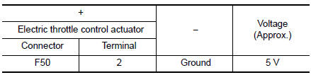
2.CHECK THROTTLE POSITION SENSOR POWER SUPPLY
- Turn ignition switch OFF.
- Disconnect electric throttle control actuator harness connector.
- Turn ignition switch ON.
- Check the voltage between electric throttle control actuator harness connector and ground.
Is the inspection result normal? YES >> GO TO 4.
NO >> GO TO 3.
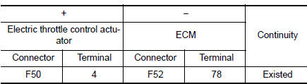
3.CHECK THROTTLE POSITION SENSOR POWER SUPPLY CIRCUIT
- Turn ignition switch OFF.
- Disconnect ECM harness connector.
- Check the continuity between electric throttle control actuator harness connector and ground.
- Also check harness for short to ground.
Is the inspection result normal? YES >> Perform the trouble diagnosis for power supply circuit.
NO >> Repair or replace error-detected parts.
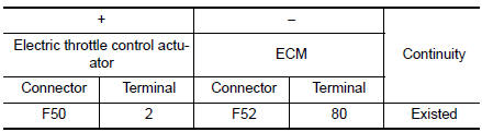
4.CHECK THROTTLE POSITION SENSOR GROUND CIRCUIT
- Turn ignition switch OFF.
- Disconnect ECM harness connector.
- Check the continuity between electric throttle control actuator harness connector and ECM harness connector.
- Also check harness for short to power.
Is the inspection result normal? YES >> GO TO 5.
NO >> Repair or replace error-detected parts.
5.CHECK THROTTLE POSITION SENSOR INPUT SIGNAL CIRCUIT
- Check the continuity between electric throttle control actuator harness connector and ECM harness connector.
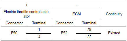
- Also check harness for short to ground and to power.
Is the inspection result normal? YES >> GO TO 6.
NO >> Repair open circuit or short to ground or short to power in harness or connectors.
6.CHECK THROTTLE POSITION SENSOR
Check the throttle position sensor. Refer to EC-448, "Component Inspection".
Is the inspection result normal? YES >> GO TO 7.
NO >> Replace electric throttle control actuator. Refer to EM-26, "Removal and Installation".
7.CHECK INTERMITTENT INCIDENT
Refer to GI-41, "Intermittent Incident".
>> INSPECTION END
Component Inspection
1.CHECK THROTTLE POSITION SENSOR
- Turn ignition switch OFF.
- Reconnect all harness connectors disconnected.
- Perform “ Throttle Valve Closed Position Learning”. Refer to EC-140, "Work Procedure".
- Turn ignition switch ON.
- Set selector lever to D position.
- Check the voltage between ECM harness connector terminals as per the following condition
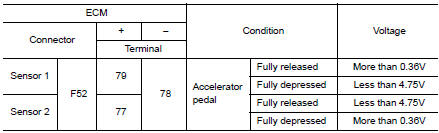
Is the inspection result normal? YES >> INSPECTION END
NO >> Replace electric throttle control actuator. Refer to EM-26, "Removal and Installation".
 P2127, P2128 APP sensor
DTC Description
DTC DETECTION LOGIC
DTC No.
CONSULT screen terms
(Trouble diagnosis content)
DTC detecting condition
P2127
APP SEN 2/CIRC
(Throttle/pedal position sens ...
 P2138 APP sensor
DTC Description
DTC DETECTION LOGIC
DTC No.
CONSULT screen terms
(Trouble diagnosis content)
DTC detecting condition
P2138
APP SENSOR
(Throttle/pedal position sensor/s ...
Other materials:
B1429 seat belt buckle switch RH
Description
DTC B1429 SEAT BELT BUCKLE SWITCH RH
The air bag diagnosis sensor unit monitors the seat belt buckle switch RH
status. If the control unit detects an
open or short condition in the circuit, it will set the DTC.
PART LOCATION
Refer to SRC-6, "Component Parts Location".
D ...
Does not operate
Description
VDC function, TCS function, ABS function, EBD function, Brake limited slip
differential (BLSD) function, Brake
assist function, hill start assist function or Brake force distribution function
does not operate.
Diagnosis Procedure
CAUTION:
VDC function, TCS function, ABS ...
Cup holders
Front console
Bench seat
CAUTIONDo not recline the rear seatback when you
use the cup holders on the rear armrest.
Doing so may cause the beverages to spill
over, and if they are hot, they may scald
the passengers.
CAUTION
Avoid abrupt star ...
