Nissan Rogue Service Manual: P0779 pressure control solenoid B
DTC Description
DTC DETECTION LOGIC
| DTC | CONSULT screen terms (Trouble diagnosis content) | DTC detection condition |
| P0779 | Pressure control solenoid B Inte | When all of the following conditions are satisfied and this state is
maintained
for 0.2 seconds:
|
POSSIBLE CAUSE
- Harness or connector (Secondary pressure solenoid valve circuit open or shorted to power supply)
- Secondary pressure solenoid valve
FAIL-SAFE
- Selector shock is large
- Start is slow
- Acceleration is slow
- Lock-up is not performed
DTC CONFIRMATION PROCEDURE
1.PREPARATION BEFORE WORK
If another "DTC CONFIRMATION PROCEDURE" occurs just before, turn ignition switch OFF and wait for at least 10 seconds, then perform the next test.
>> GO TO 2.
2.CHECK DTC DETECTION
- Start the engine.
- Drive the vehicle.
- Maintain the following conditions for 5 seconds or more.
Selector lever : “D” position
Vehicle speed : 40 km/h (25 MPH) or more
- Stop the vehicle.
- Check the first trip DTC.
Is “P0779” detected? YES >> Go to TM-143, "Diagnosis Procedure".
NO-1 >> To check malfunction symptom before repair: Refer to GI-41, "Intermittent Incident".
NO-2 >> Confirmation after repair: INSPECTION END
Diagnosis Procedure
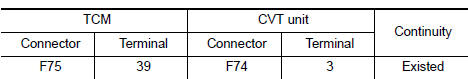
1.CHECK CIRCUIT BETWEEN TCM AND CVT UNIT
- Turn ignition switch OFF.
- Disconnect TCM connector and CVT unit connector.
- Check continuity between TCM harness connector terminal and CVT unit harness connector terminal.
Is the inspection result normal?
YES >> GO TO 2.
NO >> Repair or replace damaged parts.
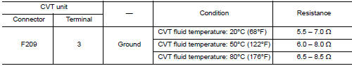
2.CHECK CIRCUIT BETWEEN CVT UNIT AND GROUND
Check continuity between CVT unit harness connector terminal and ground.
Is the inspection result normal? YES >> INSPECTION END
NO >> There is malfunction of secondary pressure solenoid valve. Replace transaxle assembly. Refer to TM-220, "Removal and Installation".
 P0778 pressure control solenoid B
DTC Description
DTC DETECTION LOGIC
DTC
CONSULT screen terms
(Trouble diagnosis content)
DTC detection condition
P0778
PC SOLENOID B
(Pressure Control Solenoid “B” ...
 P0841 transmission fluid pressure SEN/SW A
DTC Description
DTC DETECTION LOGIC
DTC
CONSULT screen terms
(Trouble diagnosis content)
DTC detection condition
P0841
FLUID PRESS SEN/SW A
(Transmission Fluid Pressur ...
Other materials:
Power window motor
DRIVER SIDE
DRIVER SIDE : Description
Door glass moves UP/DOWN by receiving the signal from main power window and
door lock/unlock switch.
DRIVER SIDE : Component Function Check
1. CHECK FRONT POWER WINDOW MOTOR LH OPERATION
Check front power window motor LH operation with main power window a ...
Fuel pressure
Work Procedure
FUEL PRESSURE RELEASE
1.FUEL PRESSURE RELEASE
With CONSULT
Turn ignition switch ON.
Perform “FUEL PRESSURE RELEASE” in “WORK SUPPORT” mode of “ENGINE”
using CONSULT.
Start engine.
After engine stalls, crank it two or three times to ...
P0448 EVAP canister vent control valve
DTC Description
DTC DETECTION LOGIC
DTC No.
CONSULT screen terms
(Trouble diagnosis content)
DTC detecting condition
P0448
VENT CONTROL VALVE
(Evaporative emission system vent control
circuit shorted)
EVAP canister vent control valve remains closed under specif ...
