Nissan Rogue Service Manual: P0715 input speed sensor A
DTC Description
DTC DETECTION LOGIC
| DTC | CONSULT screen terms (Trouble diagnosis content) | DTC detection condition |
| P0715 | INPUT SPEED SENSOR A (Input/Turbine Speed Sensor A Circuit) | When 1 is satisfied and any of 2, 3 or 4 is satisfied:
|
POSSIBLE CAUSE
- Harness or connector (Primary speed sensor circuit is open or shorted)
- Primary speed sensor
FAIL-SAFE
- Start is slow
- Acceleration is slow
- Lock-up is not performed
DTC CONFIRMATION PROCEDURE
CAUTION: Be careful of the driving speed.
1.PREPARATION BEFORE WORK
If another "DTC CONFIRMATION PROCEDURE" occurs just before, turn ignition switch OFF and wait for at least 10 seconds, then perform the next test.
>> GO TO 2.
2.CHECK DTC DETECTION
- Start the engine.
- Drive the vehicle.
- Maintain the following conditions for 10 seconds or more.
Selector lever : “D” POSITION
Engine speed : 1,200 rpm or more
Vehicle speed : 40 km/h (25 MPH) or more
- Stop the vehicle.
- Check the first trip DTC.
Is “P0715” detected? YES >> Go to TM-126, "Diagnosis Procedure".
NO-1 >> To check malfunction symptom before repair: Refer to GI-41, "Intermittent Incident".
NO-2 >> Confirmation after repair: INSPECTION END
Diagnosis Procedure
1.CHECK PRIMARY SPEED SENSOR POWER CIRCUIT
- Turn ignition switch OFF.
- Disconnect primary speed sensor connector.
- Turn ignition switch ON.
- Check voltage between primary speed sensor harness connector terminal and ground.
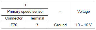
Is the inspection result normal? YES >> GO TO 2.
NO >> GO TO 6.
2.CHECK PRIMARY SPEED SENSOR GROUND CIRCUIT
Check continuity between primary speed sensor harness connector terminal and ground.
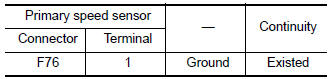
Is the inspection result normal? YES >> GO TO 3.
NO >> Repair or replace malfunctioning parts.
3.CHECK CIRCUIT BETWEEN PRIMARY SPEED SENSOR AND TCM (PART 1)
- Turn ignition switch OFF.
- Disconnect TCM connector.
- Check continuity between primary speed sensor harness connector terminal and TCM harness connector terminal.
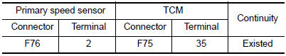
Is the inspection result normal? YES >> GO TO 4.
NO >> Repair or replace malfunctioning parts.
4.CHECK CIRCUIT BETWEEN PRIMARY SPEED SENSOR AND TCM (PART 2)
Check continuity between primary speed sensor harness connector terminal and ground.
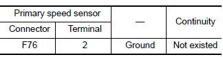
Is the inspection result normal?
YES >> GO TO 5.
NO >> Repair or replace malfunctioning parts.
5.CHECK TCM INPUT SIGNALS
- Connect all of disconnected connectors.
- Lift the vehicle.
- Start the engine.
- Check frequency of primary speed sensor.
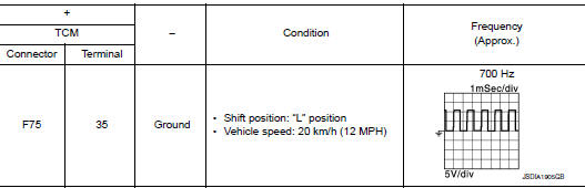
Is the inspection result normal? YES >> INSPECTION END
NO >> Replace primary speed sensor. Refer to TM-208, "Removal and Installation".
6.CHECK CIRCUIT BETWEEN IPDM E/R AND PRIMARY SPEED SENSOR
- Turn ignition switch OFF.
- Disconnect IPDM E/R connector.
- Check continuity between IPDM E/R harness connector terminal and primary speed sensor harness connector terminal.
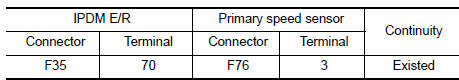
Is the check result normal? YES >> GO TO 7.
NO >> Repair or replace malfunctioning parts.
7.DETECT MALFUNCTIONING ITEMS
Check the following items:
- Open circuit or short circuit in harness between ignition switch and IPDM E/R. Refer to PG-15, "Wiring Diagram — Ignition Power Supply —".
- Short circuit in harness between IPDM E/R harness connector terminal 70 and primary speed sensor harness connector terminal 3.
- 10A fuse (No.46, located in the IPDM E/R). Refer to PG-68, "IPDM E/R Terminal Arrangement".
- IPDM E/R
Is the check result normal? YES >> INSPECTION END
NO >> Repair or replace malfunctioning parts.
 P0713 transmission fluid temperature sensor A
DTC Description
DTC DETECTION LOGIC
DTC
CONSULT screen terms
(Trouble diagnosis content)
DTC detection condition
P0713
FLUID TEMP SENSOR A
(Transmission Fluid Temperat ...
 P0717 input speed sensor A
DTC Description
DTC DETECTION LOGIC
DTC
CONSULT screen terms
(Trouble diagnosis content)
DTC detection condition
P0717
INPUT SPEED SENSOR A
(Input/Turbine Speed Sensor ...
Other materials:
Glass lid
Exploded View
Panoramic roof glass
Glass lid
Side trim covers (LH/RH)
Front drain hose (LH/RH)
Moonroof motor assembly
Sunshade motor assembly
Moonroof front bracket (LH/RH)
Moonroof rear bracket (LH/RH)
Rear drain hose (LH/RH)
Moonroof unit assembly ...
Symptom diagnosis
COMBINATION SWITCH SYSTEM SYMPTOMS
Symptom Table
Perform the data monitor of CONSULT to check for any malfunctioning
item.
Check the malfunction combinations.
Identify the malfunctioning part from the agreed combination and repair
or replace the part.
NORMAL OPERA ...
Warning/indicator lights and audible reminders
Anti-lock Braking System (ABS)
warning light
Brake warning light
Charge warning light
Low tire pressure warning light
Low windshield washer fluid warning light (if so
equipped)
Master warning light
Power s ...
