Nissan Rogue (T33) 2021-Present Service Manual: P0450 Evap Control System Pressure Sensor
DTC Description
DTC DETECTION LOGIC
| DTC |
CONSULT screen terms (Trouble diagnosis content) |
DTC detection condition | ||
| P0450 | 00 |
EVAP SYS PRES SEN (EVAP System Pressure Sensor/Switch "A" Circuit) |
Diagnosis condition | ŌĆö |
| Signal (terminal) | EVAP control system pressure sensor signal | |||
| Threshold | An excessively low or high voltage from the sensor is sent to ECM | |||
| Diagnosis delay time | ŌĆö | |||
POSSIBLE CAUSE
-
Harness or connectors (EVAP control system pressure sensor circuit is shorted.)
-
EVAP control system pressure sensor
-
Sensor power supply 3 circuit
FAIL-SAFE
Not applicable
DTC Confirmation Procedure
PRECONDITIONING
If DTC Confirmation Procedure has been previously conducted, always perform the following procedure before conducting the next test.
-
Turn ignition switch OFF and wait at least 10 seconds.
-
Turn ignition switch ON.
-
Turn ignition switch OFF and wait at least 10 seconds.
TESTING CONDITION:
Always perform test at a temperature of 5┬░C (41┬░F) or more.
>>
GO TO 2.
PERFORM DTC CONFIRMATION PROCEDURE
 With CONSULT
-
Start engine and warm it up to normal operating temperature.
-
Turn ignition switch OFF and wait at least 10 seconds.
-
Turn ignition switch ON.
-
Select ŌĆ£DATA MONITORŌĆØ mode of ŌĆ£ENGINEŌĆØ using CONSULT.
-
Make sure that ŌĆ£FUEL T/TMP SEŌĆØ indication is more than 0┬░C (32┬░F).
-
Start engine and wait at least 20 seconds.
-
Check 1st trip DTC.
 With GST
-
Start engine and warm it up to normal operating temperature.
-
Set voltmeter probes to ECM harness connector terminals as per the following.
ECM Voltage Connector + ŌłÆ Terminal E21 133 155 Less than 4.2 V -
Make sure that the voltage is less than 4.2 V.
-
Turn ignition switch OFF and wait at least 10 seconds.
-
Start engine and wait at least 20 seconds.
-
Check 1st trip DTC.
Is 1st trip DTC detected?
YES>>Proceed to DTC Diagnosis Procedure.
NO-1>>To check malfunction symptom before repair: Refer to Intermittent Incident.
NO-2>>Confirmation after repair: INSPECTION END
DTC Diagnosis Procedure
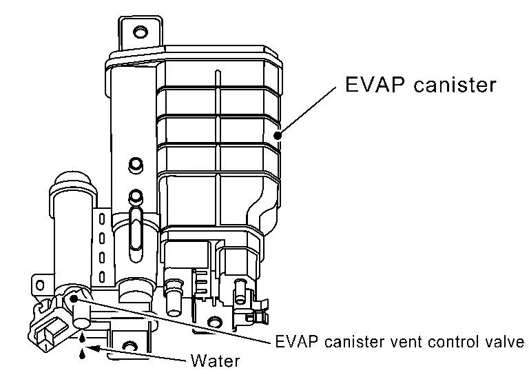
CHECK EVAP CONTROL SYSTEM PRESSURE SENSOR CONNECTOR FOR WATER
-
Turn ignition switch OFF.
-
Disconnect EVAP control system pressure sensor harness connector.
-
Check sensor harness connector for water.
Water should not exist.
Is the inspection result normal?
YES>>GO TO 2.
NO>>Repair or replace harness connector.
CHECK EVAP CONTROL SYSTEM PRESSURE SENSOR POWER SUPPLY
-
Turn ignition switch ON.
-
Check the voltage between EVAP control system pressure sensor harness connector and ground.
+ ŌłÆ Voltage
(Approx.)EVAP control system pressure sensor Connector Terminal C51 3 Ground 5 V
Is the inspection result normal?
YES>>GO TO 4.
NO>>GO TO 3.
CHECK EVAP CONTROL SYSTEM PRESSURE SENSOR POWER SUPPLY CIRCUIT
-
Turn ignition switch OFF.
-
Disconnect ECM harness connector.
-
Check the continuity between EVAP control system pressure sensor harness connector and ECM harness connector.
+ ŌłÆ Continuity EVAP control system pressure sensor ECM Connector Terminal Connector Terminal C51 3 E21 133 Existed -
Also check harness for short to ground and to power.
Is the inspection result normal?
YES>>Perform the trouble diagnosis for power supply circuit.
NO>>Repair or replace error-detected parts
CHECK EVAP CONTROL SYSTEM PRESSURE SENSOR GROUND CIRCUIT
-
Turn ignition switch OFF.
-
Disconnect ECM harness connector.
-
Check the continuity between EVAP control system pressure sensor harness connector and ECM harness connector.
+ ŌłÆ Continuity EVAP control system pressure sensor ECM Connector Terminal Connector Terminal C51 1 E21 155 Existed -
Also check harness for short to power.
Is the inspection result normal?
YES>>GO TO 5.
NO>>Repair or replace error-detected parts.
CHECK EVAP CONTROL SYSTEM PRESSURE SENSOR SIGNAL CIRCUIT
-
Check the continuity between EVAP control system pressure sensor harness connector and ECM harness connector.
+ ŌłÆ Continuity EVAP control system pressure sensor ECM Connector Terminal Connector Terminal C51 2 E21 129 Existed -
Also check harness for short to ground and to power.
Is the inspection result normal?
YES>>GO TO 6.
NO>>Repair or replace error-detected parts.
CHECK RUBBER TUBE
-
Disconnect rubber tube connected to EVAP canister vent control valve.
-
Check the rubber tube for clogging.
Is the inspection result normal?
YES>>GO TO 7.
NO>>Clean the rubber tube using an air blower, repair or replace rubber tube.
CHECK EVAP CANISTER VENT CONTROL VALVE
Refer to Component Inspection.
Is the inspection result normal?
YES>>GO TO 8.
NO>>Replace EVAP canister vent control valve. Refer to Removal and Installation.
CHECK IF EVAP CANISTER IS SATURATED WITH WATER
-
Remove EVAP canister with EVAP canister vent control valve and EVAP control system pressure sensor attached.
-
Check if water will drain from the EVAP canister.
Does water drain from EVAP canister?
YES>>GO TO 9.
NO>>Check intermittent incident. Refer to Intermittent Incident.
CHECK EVAP CANISTER
Weigh the EVAP canister with the EVAP canister vent control valve and EVAP control system pressure sensor attached.
The weight should be less than 2.3 kg (5.1 lb).
Is the inspection result normal?
YES>>Check intermittent incident. Refer to Intermittent Incident.
NO>>GO TO 10.
DETECT MALFUNCTIONING PART
Check the following.
-
EVAP canister for damage
-
EVAP hose between EVAP canister and Nissan Ariya vehicle frame for clogging or poor connection
Is the inspection result normal?
YES>>Replace EVAP control system pressure sensor. Refer to Removal and Installation.
NO>>Repair hose or replace EVAP canister. Refer to Removal and Installation.
Other materials:
Removal and Installation. Map Lamp
Exploded View
Headlining assembly
Map lamp assembly
Map lamp housing
Bulb
Lens
Map lamp finisher
: Pawl
: Metal clip
Removal and Installation
REMOVALCAUTION:
Disconnect the battery negative terminal or remove power
circuit fuse when performing t ...
P0420 Three Way Catalyst Function
DTC Description
The ECM monitors the switching frequency ratio of air fuel ratio (A/F) sensor 1 and heated oxygen sensor 2.A
three way catalyst (manifold) with high oxygen storage capacity will
indicate a low switching frequency of heated oxygen sensor 2. As oxygen
storage capacity decreases, ...
P0461 Fuel Level Sensor
DTC Description
DTC DETECTION LOGICDriving long distances naturally affect fuel gauge level.This diagnosis detects the fuel gauge malfunction of the gauge not moving even after a long distance has been driven. DTC
CONSULT screen terms
(Trouble diagnosis content)
DTC detection condition
...