Nissan Rogue (T33) 2021-Present Service Manual: P0181 Ftt Sensor
DTC Description
DTC DETECTION LOGIC
| DTC |
CONSULT screen terms (Trouble diagnosis content) |
DTC detection condition | |||
| P0181 | 00 |
FTT SENSOR (Fuel temperature sensor ″A″ circuit range/performance) |
A | Diagnosis condition | — |
| Signal (terminal) | Fuel tank temperature sensor signal | ||||
| Threshold | Rationally incorrect voltage from the sensor is sent to ECM, compared with the voltage signals from ECT sensor and intake air temperature sensor. | ||||
| Diagnosis delay time | — | ||||
| B | Diagnosis condition | Engine cold start | |||
| Signal (terminal) | Fuel tank temperature sensor signal | ||||
| Threshold | The comparison result of signals transmitted to ECM from each temperature sensor (IAT sensor, ECT sensor, EOT sensor, and FTT sensor) shows that the voltage signal of the FTT sensor is higher/lower than that of other temperature sensors when the engine is started with its cold state. | ||||
| Diagnosis delay time | — | ||||
POSSIBLE CAUSE
Malfunction A
-
Harness or connectors (FTT sensor circuit is open or shorted)
-
Fuel tank temperature sensor
Malfunction B
-
Harness or connectors (High or low resistance in the FTT sensor circuit)
-
Fuel tank temperature sensor
FAIL-SAFE
Not applicable
DTC CONFIRMATION PROCEDURE
INSPECTION START
Is it necessary to erase permanent DTC?
YES>>GO TO 7.
NO>>GO TO 2.
PRECONDITIONING
If DTC Confirmation Procedure has been previously conducted, always turn ignition switch OFF and wait at least 10 seconds before conducting the next test.
>>
GO TO 3.
PERFORM DTC CONFIRMATION PROCEDURE FOR MALFUNCTION A-1
-
Turn ignition switch ON and wait at least 10 seconds.
-
Check 1st trip DTC.
Is 1st trip DTC detected?
YES>>DTC Diagnosis Procedure
NO>>GO TO 4.
CHECK ENGINE COOLANT TEMPERATURE
 With CONSULT
-
Select “COOLANT TEMP/S” in “DATA MONITOR” mode of “ENGINE” using CONSULT.
-
Check “COOLANT TEMP/S” value.
 With GST
Follow the procedure “With CONSULT” above.
“COOLANT TEMP/S” less than 60°C (140°F)?
YES-1>>To check malfunction symptom before repair: Refer to Intermittent Incident.
YES-2>>Confirmation after repair: INSPECTION END
NO>>GO TO 5.
PERFORM DTC CONFIRMATION PROCEDURE FOR MALFUNCTION A-2
With CONSULT
-
Cool engine down until “COOLANT TEMP/S” is less than 60°C (140°F).
-
Wait at least 10 seconds.
-
Check 1st trip DTC.
With GST
Follow the procedure “With CONSULT” above.
Is 1st trip DTC detected?
YES>>DTC Diagnosis Procedure
NO>>GO TO 6.
PERFORM COMPONENT FUNCTION CHECK FOR MALFUNCTION B
 NOTE:
NOTE:
Use the component function check to check the overall function of the FTT sensor circuit. During this check, a 1st trip DTC might not be confirmed.
-
Turn ignition switch OFF.
-
Disconnect fuel level sensor unit and fuel pump harness connector.
-
Remove “fuel level sensor unit, fuel filter and fuel pump assembly”. Refer to Removal and Installation(AWD), Removal and Installation(FWD).
-
Check resistance between fuel level sensor unit and fuel pump terminals by heating with hot water as shown in the figure.
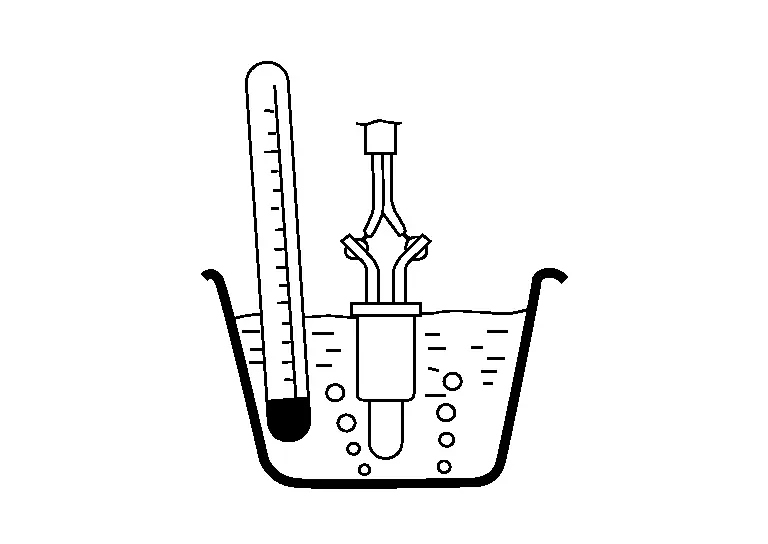
Fuel level sensor unit and fuel pump Condition Resistance Terminal 8 7 Temperature [°C (°F)] 20 (68) 2.3 – 2.7 kΩ 50 (122) 0.79 – 0.90 kΩ
Is the inspection result normal?
YES-1>>To check malfunction symptom before repair: Intermittent Incident.
YES-2>>Confirmation after repair: INSPECTION END
NO>>DTC Diagnosis Procedure
PRECONDITIONING
If DTC Confirmation Procedure has been previously conducted, always turn ignition switch OFF and wait at least 10 seconds before conducting the next test.
TESTING CONDITION:
-
Before performing the following procedure, do not add fuel.
-
Before performing the following procedure, check that fuel level is between 1/4 and 4/4.
-
Before performing the following procedure, confirm that battery voltage is 11 V or more at idle.
>>
GO TO 8.
PERFORM DTC CONFIRMATION PROCEDURE
-
Move the Nissan Ariya vehicle to a cool place.
NOTE:
Cool the vehicle in an environment of ambient air temperature between −10°C (14°F) and 35°C (95°F).
-
Turn ignition switch OFF and leave the Nissan Ariya vehicle for 12 hours.
CAUTION:
Never turn ignition switch ON during this procedure.
NOTE:
The Nissan Ariya vehicle must be cooled with the hood open.
-
Start engine and let it idle for 5 minutes or more.
CAUTION:
Never turn ignition switch OFF during idling.
-
Check 1st trip DTC.
Is 1st trip DTC detected?
YES>>DTC Diagnosis Procedure
NO-1>>To check malfunction symptom before repair: Intermittent Incident.
NO-2>>Confirmation after repair: INSPECTION END
DTC Diagnosis Procedure
INSPECTION START
Confirm the detected malfunction (A or B). DTC Description
Which malfunction is detected?
A>>GO TO 2.
B>>GO TO 5.
CHECK FUEL TANK TEMPERATURE (FTT) SENSOR POWER SUPPLY
-
Turn ignition switch OFF.
-
Disconnect fuel level sensor unit and fuel pump harness connector.
-
Turn ignition switch ON.
-
Check the voltage between fuel level sensor unit and fuel pump harness connector and ground.
+ ‚àí Voltage
(Approx.)Fuel level sensor unit and fuel pump Connector Terminal B100 8 Ground 5 V
Is the inspection result normal?
YES>>GO TO 4.
NO>>GO TO 3.
CHECK FTT SENSOR POWER SUPPLY CIRCUIT
-
Turn ignition switch OFF.
-
Disconnect ECM harness connector.
-
Check the continuity between fuel level sensor unit and fuel pump harness connector and ECM harness connector.
Fuel level sensor unit and fuel pump ECM Continuity Connector Terminal Connector Terminal B100 8 E21 136 Existed -
Also check harness for short to ground and to power.
Is the inspection result normal?
YES>>Perform the trouble diagnosis for power supply circuit.
NO>>Repair or replace malfunctioning part.
CHECK FTT SENSOR GROUND CIRCUIT
-
Turn ignition switch OFF.
-
Disconnect ECM harness connector.
-
Check the continuity between fuel level sensor unit and fuel pump harness connector and ECM harness connector.
Fuel level sensor unit and fuel pump ECM Continuity Connector Terminal Connector Terminal B100 7 E21 155 Existed -
Also check harness for short to power.
Is the inspection result normal?
YES>>GO TO 5.
NO>>Repair or replace malfunctioning part.
CHECK FTT SENSOR
Refer to Component Inspection.
Is the inspection result normal?
YES>>INSPECTION END
NO>>Replace fuel level sensor unit, fuel filter and fuel pump assembly (with fuel tank temperature sensor). Refer to Removal and Installation.
Other materials:
P00fe Evap Control System
DTC Description
This diagnosis detects clogs in the EVAP line between fuel tank and EVAP canister purge volume control solenoid valve.ECM
controls EVAP control system as below. ECM monitors EVAP line pressure
change to diagnose if there is no clogging between EVAP canister and
fuel tank.
E ...
Precaution. Precautions
Precaution for Supplemental Restraint System (SRS) "AIR BAG" and "SEAT BELT PRE-TENSIONER"
The Supplemental Restraint System such as “AIR BAG” and “SEAT BELT
PRE-TENSIONER”, used along with a front seat belt, helps to reduce the
risk or severity of injury to the driver and front passeng ...
Component Parts
Brake Control System
Component Parts Location
A.
Engine Room (LH Side)
No. Component Function
1.
Steering angle sensor
Refer to Steering Angle Sensor.
2.
Combination Meter
Refer to Component Parts Location (Type A Meter) or Component Parts Location (Type B Meter) f ...