Nissan Rogue Service Manual: P0172 fuel injection system function
DTC Description
DTC DETECTION LOGIC
With the Air/Fuel Mixture Ratio Self-Learning Control, the actual mixture ratio can be brought closely to the theoretical mixture ratio based on the mixture ratio feedback signal from the A/F sensors 1. The ECM calculates the necessary compensation to correct the offset between the actual and the theoretical ratios.
In case the amount of the compensation value is extremely large (The actual mixture ratio is too rich.), the ECM judges the condition as the fuel injection system malfunction and lights up the MIL (2 trip detection logic).
| Sensor | Input signal to ECM | ECM function | Actuator |
| A/F sensor 1 | Density of oxygen in exhaust gas (Mixture ratio feedback signal) | Fuel injection control | Fuel injector |
| DTC No. | CONSULT screen terms (Trouble diagnosis content) | DTC detecting condition |
| P0172 | FUEL SYS-RICH-B1 (System too rich bank 1) |
|
POSSIBLE CAUSE
- A/F sensor 1
- Fuel injector
- Exhaust gas leaks
- Incorrect fuel pressure
- Mass air flow sensor
FAIL-SAFE
Traveling control mode (Accelerator angle variation control)
DTC CONFIRMATION PROCEDURE
1.PRECONDITIONING
If DTC Confirmation Procedure has been previously conducted, always perform the following procedure before conducting the next test.
- Turn ignition switch OFF and wait at least 10 seconds.
- Turn ignition switch ON.
- Turn ignition switch OFF and wait at least 10 seconds.
>> GO TO 2.
2.PERFORM DTC CONFIRMATION PROCEDURE-1
- Clear the mixture ratio self-learning value. Refer to EC-143, "Work Procedure".
- Start engine.
Is it difficult to start engine? YES >> GO TO 3.
NO >> GO TO 4.
3.RESTART ENGINE
If it is difficult to start engine, the fuel injection system has a malfunction, too.
Crank engine while depressing accelerator pedal.
NOTE: When depressing accelerator pedal three-fourths (3/4) or more, the control system does not start the engine. Do not depress accelerator pedal too much.
Does engine start? YES >> Proceed to EC-266, "Diagnosis Procedure".
NO >> Check exhaust and intake air leak visually.
4.PERFORM DTC CONFIRMATION PROCEDURE-2
- Start engine and let it idle for at least 5 minutes.
- Check 1st trip DTC.
Is 1st trip DTC detected? YES >> Proceed to EC-266, "Diagnosis Procedure".
NO >> GO TO 5.
5.PERFORM DTC CONFIRMATION PROCEDURE-3
- Turn ignition switch OFF and wait at least 10 seconds.
- Start engine.
- Maintain the following conditions for at least 10 consecutive
minutes.
Hold the accelerator pedal as steady as possible.

CAUTION: Always drive vehicle at a safe speed.
- Check 1st trip DTC.
Is 1st trip DTC detected? YES >> Proceed to EC-266, "Diagnosis Procedure".
NO >> INSPECTION END
Diagnosis Procedure
1.CHECK EXHAUST GAS LEAK
- Start engine and run it at idle.
- Listen for an exhaust gas leak before three way catalyst (manifold).
Is exhaust gas leak detected? YES >> Repair or replace error-detected parts.
NO >> GO TO 2.
2.CHECK FOR INTAKE AIR LEAK
- Listen for an intake air leak after the mass air flow sensor.
- Check PCV hose connection.
Intake air leak detected? YES >> Repair or replace error-detected parts.
NO >> GO TO 3.
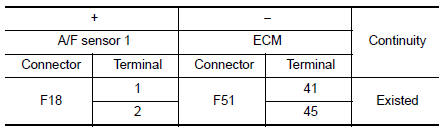
3.CHECK A/F SENSOR 1 INPUT SIGNAL CIRCUIT
- Turn ignition switch OFF.
- Disconnect corresponding A/F sensor 1 harness connector.
- Disconnect ECM harness connector.
- Check the continuity between A/F sensor 1 harness connector and ECM harness connector.
- Check the continuity between A/F sensor 1 harness connector and ground, or ECM harness connector and ground.
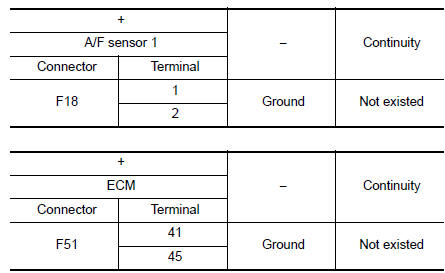
- Also check harness for short to power.
Is the inspection result normal? YES >> GO TO 4.
NO >> Repair or replace error-detected parts.
4.CHECK FUEL PRESSURE
Check fuel pressure. Refer to EC-144, "Work Procedure".
Is the inspection result normal? YES >> GO TO 6.
NO >> GO TO 5.
5. DETECT MALFUNCTIONING PART
Check fuel hoses and fuel tubes for clogging. Refer to EM-40, "Exploded View".
Is the inspection result normal? YES >> Replace “fuel filter and fuel pump assembly”. Refer to FL-6, "Removal and Installation".
NO >> Repair or replace error-detected parts.
6.CHECK MASS AIR FLOW SENSOR
 With CONSULT
- Install all removed parts.
- Start engine and warm it up to normal operating temperature.
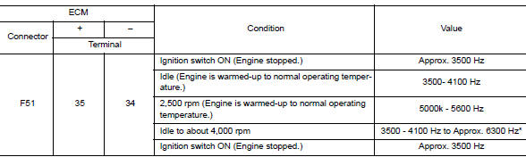
- Check “MASS AIR FLOW SENSOR (Hz)” in “DATA MONITOR” mode of “ENGINE” using CONSULT.
| Monitor item | Condition | Value |
| MASS AIR FLOW SENSOR (Hz) | Ignition switch ON (Engine stopped.) | Approx. 3500 Hz |
| Idle (Engine is warmed-up to normal operating temperature.) | 3500- 4100 Hz | |
| 2,500 rpm (Engine is warmed-up to normal operating temperature.) | 5000k - 5600 Hz | |
| Idle to about 4,000 rpm | 3500 - 4100 Hz to Approx. 6300 Hz* |
*: Check for linear frequency rise in response to engine being increased to about 4,000 rpm.
 Without consult
- Install all removed parts.
- Start engine and warm it up to normal operating temperature.
- Check mass air flow sensor signal in service $01 with gst.
*: Check for linear frequency rise in response to engine being increased to about 4,000 rpm.
Is the measurement value within the specification? YES >> GO TO 7.
NO >> Check connectors for rusted terminals or loose connections in the mass air flow sensor circuit or grounds. Refer to EC-198, "DTC Description".
7.CHECK FUNCTION OF FUEL INJECTOR
 With CONSULT
- Start engine.
- Perform “POWER BALANCE” in “ACTIVE TEST” mode of “ENGINE” using CONSULT.
- Make sure that each circuit produces a momentary engine speed drop.
 Without CONSULT
- Let engine idle.
- Listen to each fuel injector operating sound.
Clicking noise should be heard.
Is the inspection result normal? YES >> GO TO 8.
NO >> Perform trouble diagnosis for “FUEL INJECTOR”, refer to EC-464, "Component Function Check".
8.CHECK FUEL INJECTOR
- Turn ignition switch OFF.
- Confirm that the engine is cooled down and there are no fire hazards near the vehicle.
- Disconnect all fuel injector harness connectors.
- Remove fuel tube assembly. Refer to EM-40, "Removal and
Installation".
Keep fuel hose and all fuel injectors connected to fuel tube.
- Disconnect all ignition coil harness connectors.
- Prepare pans or saucers under each fuel injector.
- Crank engine for about 3 seconds.
Fuel should be sprayed evenly for each fuel injector.
Is the inspection result normal? YES >> GO TO 9.
NO >> Replace fuel injectors from which fuel does not spray out. Always replace O-ring with new ones. Refer to EM- 40, "Removal and Installation".
9.CHECK INTERMITTENT INCIDENT
Refer to GI-41, "Intermittent Incident".
>> INSPECTION EN
 P0171 fuel injection system function
DTC Description
DTC DETECTION LOGIC
With the Air/Fuel Mixture Ratio Self-Learning Control, the actual mixture
ratio can be brought closely to the
theoretical mixture ratio based on the mixture ra ...
 P0181 FTT sensor
DTC Description
DTC DETECTION LOGIC
DTC No.
CONSULT screen terms
(Trouble diagnosis content)
DTC detecting condition
P0181
FTT SENSOR
(Fuel temperature sensor ″A ...
Other materials:
B terminal circuit
Description
“B” terminal circuit supplies power to charge the battery and to operate the
vehicles electrical system.
Diagnosis Procedure
Regarding Wiring Diagram information. Refer to CHG-7, "Wiring Diagram".
1.CHECK “B” TERMINAL CONNECTION
Turn ignition switch OFF. ...
DTC/circuit diagnosis
P1610 LOCK MODE
Description
ECM forcibly switches to the mode that inhibits engine start, when engine
start operation is performed 5 times
or more while communication between ECM and BCM is not normal.
DTC Logic
DTC DETECTION LOGIC
NOTE:
If DTC B1610 is displayed with DTC U1000, fi ...
B14XX air bag diagnosis sensor unit
Description
DTC B1XXX AIR BAG DIAGNOSIS SENSOR UNIT
The air bag diagnosis sensor unit will run self diagnostics when the ignition
switch is turned ON. It has the
potential to set many diagnostic trouble codes which will conform to the B1XXX
format, but will not match any
other SRS diagnostic ...
