Nissan Rogue Service Manual: Moonroof unit assembly
Inspection
WIND DEFLECTOR
- Open glass lid fully.
- Visually check for proper installation, damaged/deteriorated components,
or foreign objects within mechanism.
Correct as required for smooth operation.
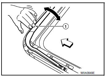
- Check for grease at the wind deflector arm (1) and pivot areas. If
necessary, apply a sufficient amount of grease for non-binding
operation.
 Front
Front
- Check that the wind deflector (1) moves freely within the moonroof
unit assembly while manually pressing down and releasing.
If a malfunction is detected, remove the moonroof unit assembly and visually inspect. If damage is found, replace either wind deflector (1) or moonroof unit assembly as required. Refer to RF-63, "Removal and Installation" (WIND DEFLECTOR) or RF- 59, "Removal and Installation" (MOONROOF UNIT ASSEMBLY).
Front
LINK AND WIRE ASSEMBLY
NOTE: Before replacing a suspect part, make sure it is the source of noise being experienced.
- Check link to determine if coating film has peeled off excessively enough that substrate is visible. Check also to determine if link is the source of noise. Replace as necessary.
- Visually check to determine if a sufficient amount of grease has been applied to wire or rail groove. If not, add grease as required.
- Check wire for any damage or deterioration. If any damage is found,
replace moonroof unit assembly.
Refer to RF-59, "Removal and Installation"
WEATHERSTRIP
- Visually check weatherstrip for damage, deterioration, or deformation.
- Open glass lid partially to inspect front edge of weatherstrip.
- Tilt up glass lid fully to inspect sides and rear edge of weatherstrip.
If any area of the weatherstrip is found to be damaged, replace the glass lid. Refer to RF-49, "Removal and Installation".
- Check for leaks around glass lid.
- Close glass lid.
- Pour water around surface to determine area of concern.
- For gaps or misalignment, adjust glass lid to specifications. Refer to ADJUSTMENT in this section.
- For damaged sealing surfaces, either replace glass lid, refer to RF-49, "Removal and Installation" or repair the panel.
DRAIN HOSES
- Front pillar
- Moonroof unit assembly
- Rear pillar
- Rear drain hoses (LH/RH)
- Front drain hoses (LH/RH)
- Remove the headlining. Refer toINT-30, "Removal and Installation".
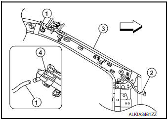
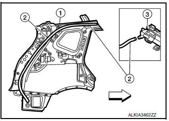
- From the inside front pillar (3) visually check drain hoses (1) for:
- Proper connection at moonroof unit assembly (4) and drain hose connection at the exit base (2).
- Damage, pinch, cracks, deterioration.
 Front
Front
- Pour water through drain hoses to determine watertight performance.
If damaged or leaking portions in any drain hose is found, replace entire drain hose as necessary.
- From the inside of the rear quarter panel (1) visually check drain hoses (2) for damage, pinching, cracks, or deterioration.
- Check for proper connection at moonroof unit assembly (3) and
drain hose (2) and for proper routing along the rear inner quarter
panel (1).Front
ADJUSTMENT
CAUTION:
- Always work with a helper.
- Handle glass lid with care to prevent damage.
NOTE:
- For easier and more accurate installation, always mark each point before removal.
- After any adjustment, check moonroof operation and glass lid alignment.
- Roof panel
- Weatherstrip
- Glass lid/panoramic roof glass
Front
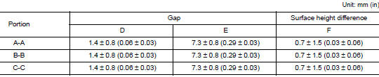
Gap adjustment (Front and Rear)
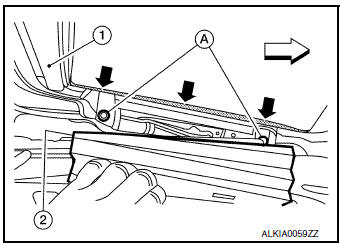
- Open sunshade (1).: Front
- Tilt glass lid up, then release side trim cover (2) on each side
and set aside.
NOTE: LH side shown; RH similar.
- Loosen glass lid bolts (A) (two each on LH and RH side), then tilt glass lid down.
- Manually adjust glass lid from outside of vehicle until gaps A-A
and C-C are within specification.
NOTE: Temporarily loosely tighten glass lid bolts to prevent movement between each adjustment.
- Tilt glass lid up and down several times using moonroof switch to check that it operates smoothly.
- Tilt glass lid up and tighten bolts.
NOTE: First tighten left front bolt, then right rear bolt on glass lid to prevent uneven torque while tightening remaining bolts.
- Attach side trim covers (LH/RH), then tilt glass lid down.
Gap Adjustment (Sides)
The moonroof unit assembly is mounted on locator pins and adjustment from side to side cannot be performed.
Surface Height Adjustment
- Tilt glass lid up and down several times using moonroof switch to check that it operates smoothly.
- Check height difference between roof surface and glass lid surface, then compare to specifications.
- If necessary, adjust height difference by using the following procedure.
- Loosen glass lid bolts.
- Manually raise/lower glass lid until height difference is within specification.
NOTE: If necessary, shims may be added between moonroof unit assembly and roof to increase adjustment range. Refer to RF-49, "Removal and Installation". Temporarily loosely tighten moonroof unit assembly bolts to prevent movement between each adjustment.
- Tilt glass lid up and down several times using moonroof switch to check that it operates smoothly.
- Tighten glass lid and moonroof side bracket bolts.
NOTE: First tighten left front bolt, then right rear bolt on glass lid to prevent uneven torque while tightening remaining bolts.
- After any adjustment, check moonroof operation and glass lid alignment.
Exploded View
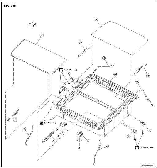
- Panoramic roof glass
- Glass lid
- Side trim covers (LH/RH)
- Front drain hose (LH/RH)
- Moonroof motor assembly
- Sunshade motor assembly
- Moonroof front bracket (LH/RH)
- Moonroof rear bracket (LH/RH)
- Rear drain hose (LH/RH)
- Moonroof unit assembly
- Rear trim covers (LH/RH)
Front
Removal and Installation
REMOVAL
CAUTION:
- Always work with a helper.
- When taking moonroof unit assembly out, use cloths to protect the seats and trim from damage.
- Remove headlining. Refer to INT-30, "Removal and Installation".
- Disconnect drain hoses (front/rear) from moonroof unit assembly. Refer to RF-55, "Inspection".
- Disconnect harness connectors from moonroof motor assembly and sunshade motor assembly.
- Remove nuts, then using a helper carefully lift each side and remove moonroof unit assembly out back of vehicle.
WARNING: Bodily injury may occur if moonroof unit assembly is not supported properly when removing.
INSTALLATION
Installation is in the reverse order of removal.
CAUTION: After installing the moonroof unit assembly, perform the leak test and check that there is no air or water intrusion. Refer to RF-55, "Inspection".
 Moonroof motor assembly
Exploded View
Panoramic roof glass
Glass lid
Side trim covers (LH/RH)
Front drain hose front (LH/RH)
Moonroof motor assembly
Sunshade motor assembly
Moonroof front bracke ...
 Sunshade
Removal and Installation
REMOVAL
Remove the moonroof unit assembly. Refer to RF-53, "Removal and
Installation".
Place the moonroof unit assembly (1) on a flat surface upside
down ...
Other materials:
Periodic maintenance
IN-CABIN MICROFILTER
Removal and Installation
REMOVAL
Release the tab and remove the in-cabin microfilter cover (1)
from under the RH side of the instrument panel.
CAUTION:
Use care when lifting up on the tab to avoid damaging it.
Remove the in-cabin microfilter (2).
CAUT ...
Remote keyless entry system (if so equipped)
WARNING
Radio waves could adversely affect
electric medical equipment. Those who
use a pacemaker should contact the
electric medical equipment manufacturer
for the possible influences before
use.
The remote keyless entry keyfob transmits
radio waves ...
DTC/circuit diagnosis
P1610 LOCK MODE
Description
ECM forcibly switches to the mode that inhibits engine start, when engine
start operation is performed 5 times
or more while communication between ECM and BCM is not normal.
DTC Logic
DTC DETECTION LOGIC
NOTE:
If DTC B1610 is displayed with DTC U1000, fi ...
