Nissan Rogue (T33) 2021-Present Service Manual: Manual Air Conditioning :: Removal and Installation
A/c Switch Assembly
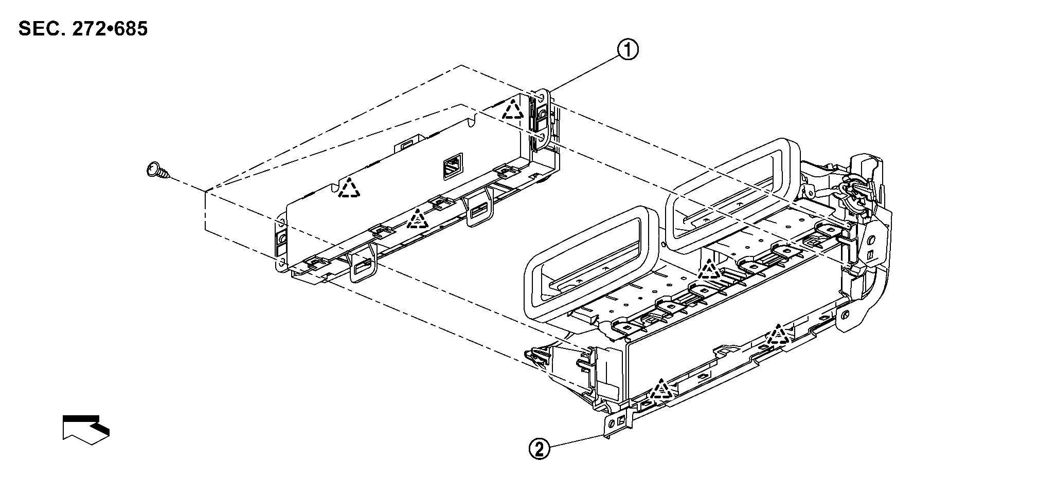
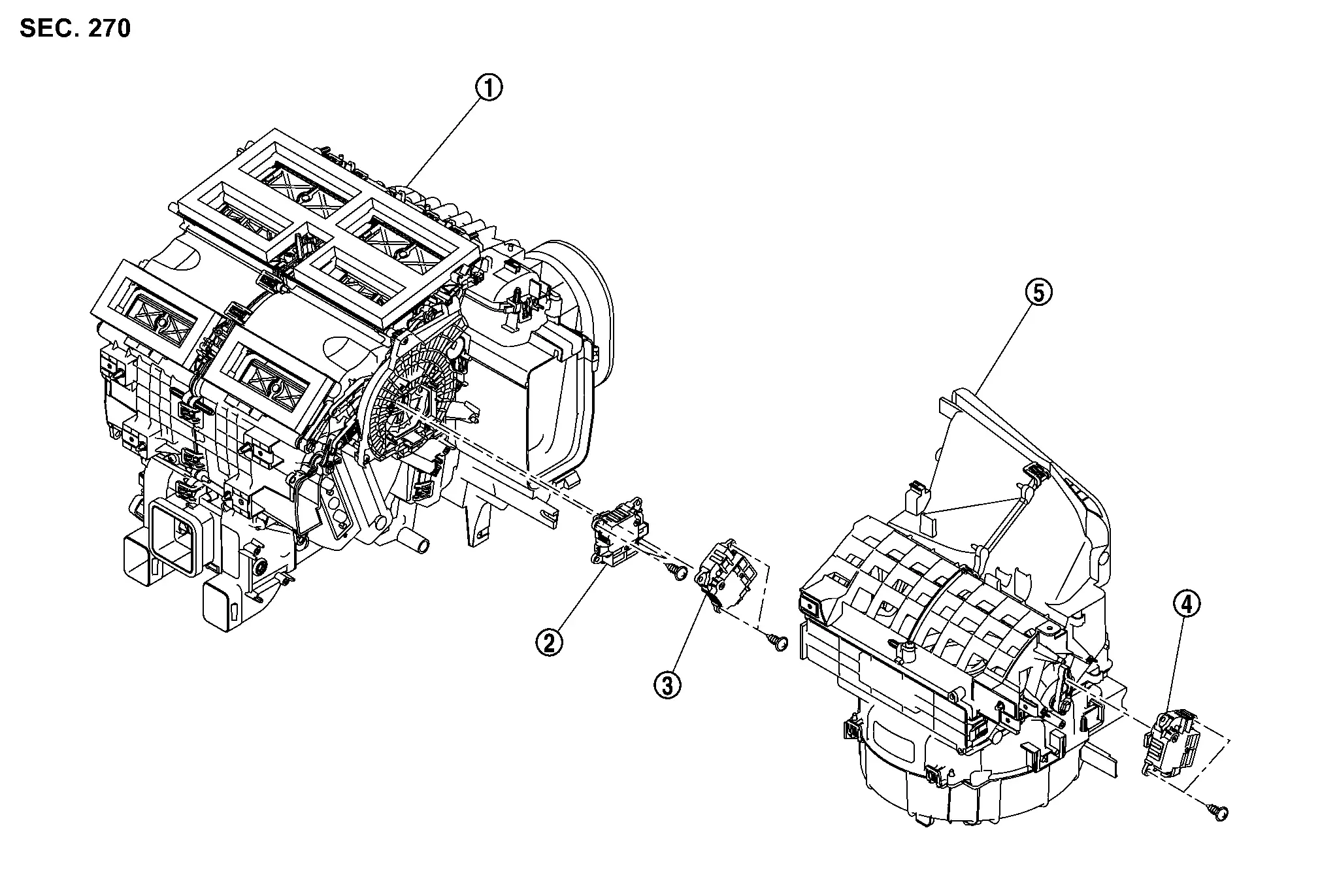
Exploded View
 |
A/C switch assembly |  |
Center ventilator finisher | ||
 |
: Pawl | ||||
| : Nissan Ariya Vehicle front | |||||
Removal and Installation
REMOVAL
Remove center ventilator finisher. Refer to Removal and Installation.
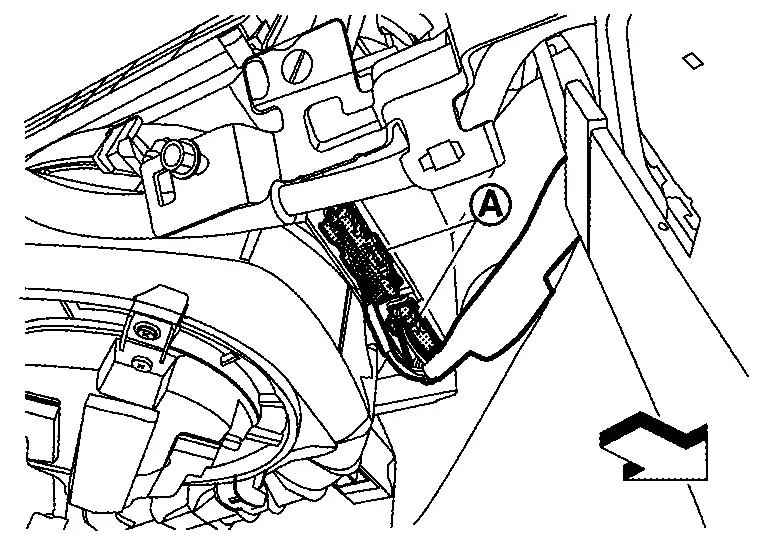
Remove A/C switch assembly fixing screws  .
.
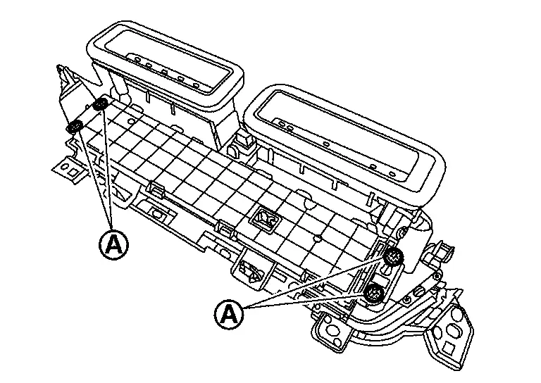
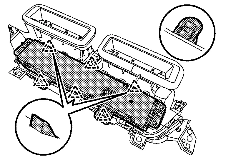
Disengage fixing pawls, and then remove A/C switch assembly.
|
: Pawl |
INSTALLATION
Install in the reverse order of removal.
A/c Amp.
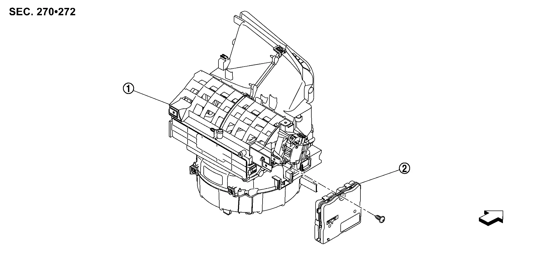
Exploded View
|
Blower unit | |
A/C amp. | ||
| : Nissan Ariya Vehicle front | |||||
Removal and Installation
REMOVAL
Remove glove box. Refer to Removal and Installation.
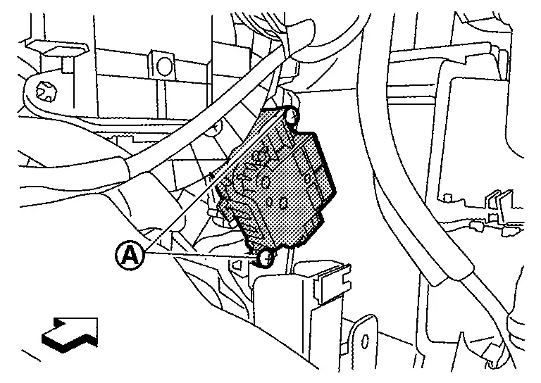
Disconnect A/C amp. harness connectors .
| : Nissan Ariya Vehicle front |
Remove fixing screw , and then slide A/C amp. in the direction indicated by arrow as shown in the figure and remove it.
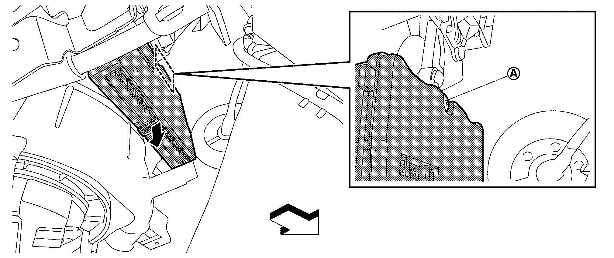
| : Nissan Ariya Vehicle front |
INSTALLATION
Note the following item, and then install in the reverse order of removal.
CAUTION:
Be sure perform ADDITIONAL SERVICE WHEN REPLACING A/C AMP. when replacing A/C amp. Or not doing so, A/C amp. control function does not operate normally. Refer to Description.
Intake Sensor
Exploded View
-
KR15DDT : Refer to Exploded View.
Removal and Installation
REMOVAL
Remove evaporator.
-
KR15DDT : Refer to Removal and Installation.
Remove intake sensor from evaporator.
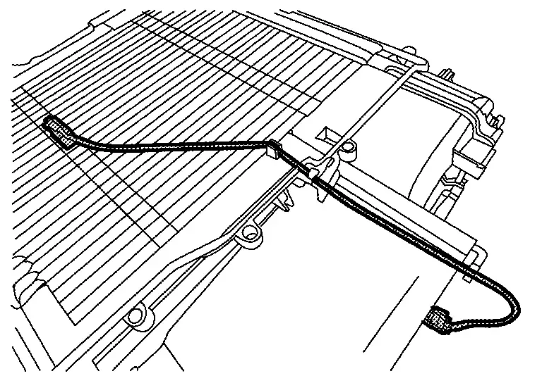
CAUTION:
-
Mark the mounting position of intake sensor bracket prior to removal so that the reinstalled sensor can be located in the same position.
-
Never damage the evaporator core.
INSTALLATION
Note the following item, and then install in the reverse order of removal.
CAUTION:
Never rotate the bracket insertion part when removing and installing the intake sensor.
Refrigerant Pressure Sensor
Exploded View
-
KR15DDT : Refer to Exploded View.
Removal and Installation
REMOVAL
-
KR15DDT : Refer to Removal and Installation.
INSTALLATION
Install in the reverse order of removal.
Ptc Heater
Exploded View
-
KR15DDT : Refer to Exploded View.
Removal and Installation
REMOVAL
Remove foot duct LH. Refer to Removal and Installation.
Disconnect PTC heater connector.
Remove fixing screws , and then remove PTC heater from heater & cooling unit assembly.
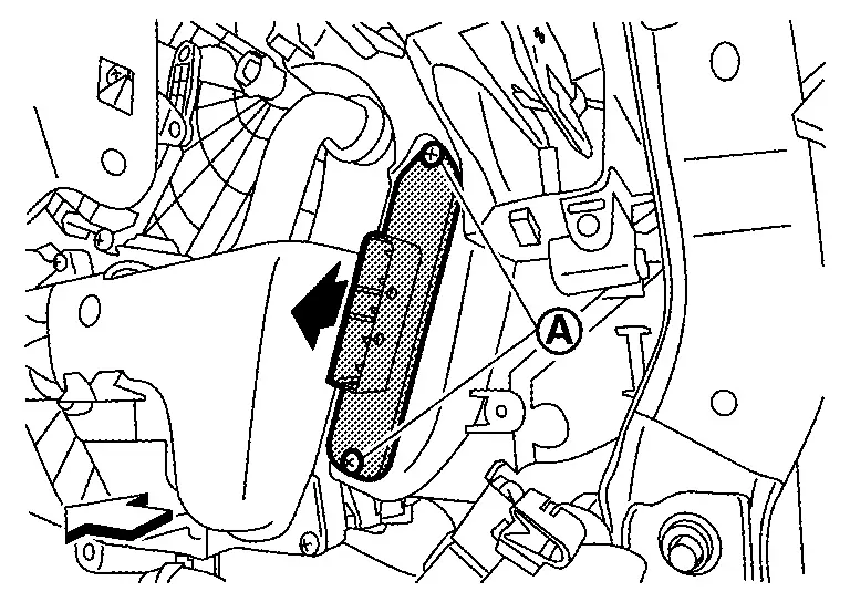
| : Nissan Ariya Vehicle front |
INSTALLATION
Install in the reverse order of removal.
Door Motor
Exploded View
|
Heater & cooling unit assembly | |
Mode door motor |  |
Air mix door motor |
 |
Intake door motor |  |
Blower unit |
Air Mix Door Motor
Removal and Installation
REMOVAL
Remove passenger knee air bag module. Refer to Removal and Installation.
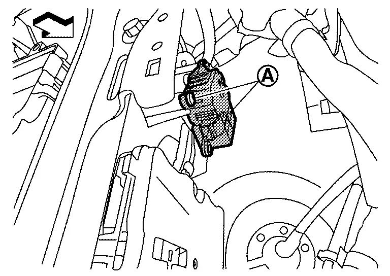
Disconnect air mix door motor harness connector.
Remove fixing screws , and then remove air mix door motor.
| : Nissan Ariya Vehicle front |
INSTALLATION
Install in the reverse order of removal.
Intake Door Motor
Removal and Installation
REMOVAL
Remove glove box. Refer to Removal and Installation.
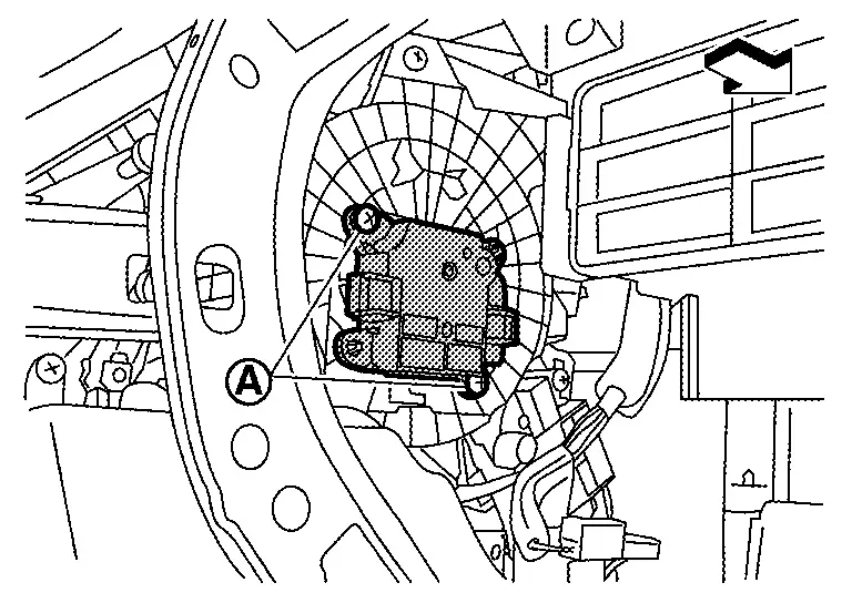
Disconnect intake door motor harness connector.
Remove fixing screws , and then remove intake door motor.
| : Nissan Ariya Vehicle front |
INSTALLATION
Install in the reverse order of removal.
Mode Door Motor
Removal and Installation
REMOVAL
Remove passenger knee air bag module. Refer to Removal and Installation.
Disconnect mode door motor harness connector.
Remove fixing screws , and then remove mode door motor.
| : Nissan Ariya Vehicle front |
INSTALLATION
Install in the reverse order of removal.
Other materials:
Dtc/circuit Diagnosis. Rear Window Defogger Switch
Component Function Check
CHECK REAR WINDOW DEFOGGER SWITCH FUNCTION
Check that the indicator lamp of rear window defogger illuminates when rear window defogger switch ON.
Is the inspection result normal?
YES>>
Rear window defogger switch function is OK.
NO>>
Refer to Diagnosis P ...
B24a4-11 Intake Sensor
DTC Description
DTC DETECTION LOGIC DTC No.
CONSULT screen terms
(Trouble diagnosis content) DTC detection condition
B24A4-11
INTAKE SENSOR
(Intake sensor)
Diagnosis condition
Ignition switch ON
Signal (Terminal)
Intake sensor signal
Threshold
The intake sensor rec ...
P023a Charge Air Cooler Cooling Electric Water Pump
DTC Description
DTC DETECTION LOGIC DTC
CONSULT screen terms
(Trouble diagnosis content)
DTC detection condition
P023A
00
Charged air cooler coolant pump
(Charge Air Cooler Coolant Pump Control Circuit/Open)
Diagnosis condition
Engine running at idle
Warm-up con ...