Nissan Rogue Service Manual: Fuel pressure
Work Procedure
FUEL PRESSURE RELEASE
1.FUEL PRESSURE RELEASE
 With CONSULT
- Turn ignition switch ON.
- Perform “FUEL PRESSURE RELEASE” in “WORK SUPPORT” mode of “ENGINE” using CONSULT.
- Start engine.
- After engine stalls, crank it two or three times to release all fuel pressure.
- Turn ignition switch OFF.
 Without CONSULT
- Remove fuel pump fuse located in IPDM E/R. For the fuse number, refer to EC-105, "Wiring Diagram". For the fuse arrangement, refer to PG-68, "IPDM E/R Terminal Arrangement".
- Start engine.
- After engine stalls, crank it two or three times to release all fuel pressure.
- Turn ignition switch OFF.
- Reinstall fuel pump fuse after servicing fuel system.
>> END
FUEL PRESSURE CHECK
CAUTION: Before disconnecting fuel line, release fuel pressure from fuel line to eliminate danger.
NOTE:
- Prepare pans or saucers under the disconnected fuel line because the fuel may spill out. The fuel pressure cannot be completely released because this models do not have fuel return system.
- Use Fuel Pressure Gauge Kit [SST: (J-44321)] to check fuel pressure.
1.FUEL PRESSURE CHECK
- Release fuel pressure to zero.
- Connect fuel tube adapter [SST:KV10120000] (B) to quick connector.
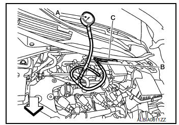
A : Fuel pressure gauge
C : Fuel feed hose
 : Vehicle front
- Turn ignition switch ON and check for fuel leakage.
- Start engine and check for fuel leakage.
- Read the indication of fuel pressure gauge
At idling : Approximately 350 kPa (3.57 kg/cm2, 51 psi)
Is the inspection result normal?
YES >> INSPECTION END
NO >> GO TO 2.
2.CHECK FUEL HOSES AND FUEL TUBES
Check fuel hoses and fuel tubes for clogging.
Is the inspection result normal? YES >> Replace “fuel filter and fuel pump assembly”. Refer to FL-6, "Removal and Installation".
NO >> Repair or replace error-detected parts.
 Mixture ratio self-learning value clear
Description
This describes how to erase the mixture ratio self-learning value. For the
actual procedure, follow the instructions
in “Diagnosis Procedure”.
Work Procedure
1.START
With CONSU ...
 How to set srt code
Description
OUTLINE
In order to set all SRTs, the self-diagnoses as in the “SRT ITEM” table must
have been performed at least
once. Each diagnosis may require actual driving for a long period ...
Other materials:
Break-in schedule
CAUTIONDuring the first 1,200 miles (2,000 km),
follow these recommendations to obtain
maximum engine performance and ensure
the future reliability and economy of your
new vehicle. Failure to follow these recommendations
may result in shortened
engine life and reduced engine ...
U1000 CAN COMM circuit
Description
CAN (Controller Area Network) is a serial communication system for real time
application. It is an on-vehicle
multiplex communication system with high data communication speed and excellent
error detection ability.
Many electronic control units are equipped into vehicles, and ea ...
Symptom diagnosis
EXTERIOR LIGHTING SYSTEM SYMPTOMS
Symptom Table
CAUTION:
Perform the self-diagnosis with CONSULT before the symptom diagnosis. Perform
the trouble diagnosis
if any DTC is detected.
NORMAL OPERATING CONDITION
Description
AUTO LIGHT SYSTEM
The headlamp may not be turned ON/OFF immedi ...
