Nissan Rogue Service Manual: Front wiper arm
Exploded View
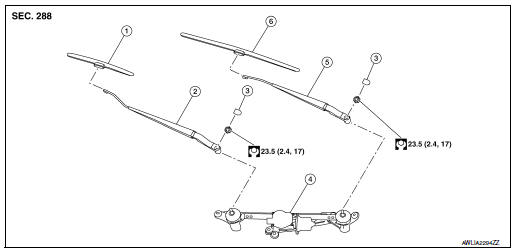
- Front wiper blade (RH)
- Front wiper arm (RH)
- Front wiper arm cover
- Front wiper drive assembly
- Front wiper arm (LH)
- Front wiper blade (LH)
Removal and Installation
REMOVAL
- Move front wiper into the service position by turning the ignition switch ON, then quickly push the wiper washer switch to the mist position two times within 0.5 seconds.
- Turn the ignition switch OFF.
- Remove front wiper arm covers.
- Remove nuts and remove front wiper arms.
INSTALLATION
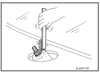
- Clean wiper arm mount as shown in the figure to prevent nuts from being loosened.
- Move front wiper into the service position by turning the ignition switch ON, then quickly push the wiper washer switch to the mist position two times within 0.5 seconds.
- Turn the ignition switch OFF.
- Adjust front wiper blade position. Refer to WW-64, "Adjustment".
- Install front wiper arm by tightening the nuts.
- Install front wiper arm covers.
- Check that the front wiper blades stop at the specified position.
Adjustment
- Wiper blade (RH)
- Front fender (RH)
- Windshield glass
- Cowl top cover
- Wiper blade (LH)
- 34.9 ± 7.5 mm (1.4 ± 0.3 in)
- 38.2 ± 7.5 mm (1.5 ± 0.3 in)
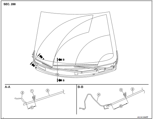
 Front washer nozzle and tube
Exploded View
Cowl top cover
Front washer tube
Front washer nozzle (LH)
Front washer nozzle (RH)
Pawl
Clip
Exploded View
Cowl top cover
Front washer tube
...
 Front wiper blade
Exploded View
Wiper blade (RH)
Wiper arm (RH)
Wiper arm cover
Front wiper drive assembly
Wiper arm (LH)
Wiper blade (LH)
Removal and Installation
REMOVAL
Move front ...
Other materials:
1564 ASCD steering switch
DTC Description
DTC DETECTION LOGIC
DTC No.
CONSULT screen terms
(Trouble diagnosis content)
DTC detecting condition
P1564
ASCD SW
(ASCD switch)
An excessively high voltage signal from the ASCD steering switch
is sent
to ECM.
ECM detect ...
Power supply and ground circuit
COMBINATION METER
COMBINATION METER : Diagnosis Procedure
Regarding Wiring Diagram information, refer to MWI-32, "Wiring Diagram".
1.CHECK FUSES
Check that the following fuses are not blown.
Is the fuse blown?
YES >> Replace the blown fuse after repairing the affected circu ...
Precaution
Precaution for Supplemental Restraint System (SRS) "AIR BAG" and "SEAT
BELT
PRE-TENSIONER"
The Supplemental Restraint System such as “AIR BAG” and “SEAT BELT PRE-TENSIONER”,
used along
with a front seat belt, helps to reduce the risk or severity of injury to the
...
