Nissan Rogue Service Manual: ECU diagnosis information
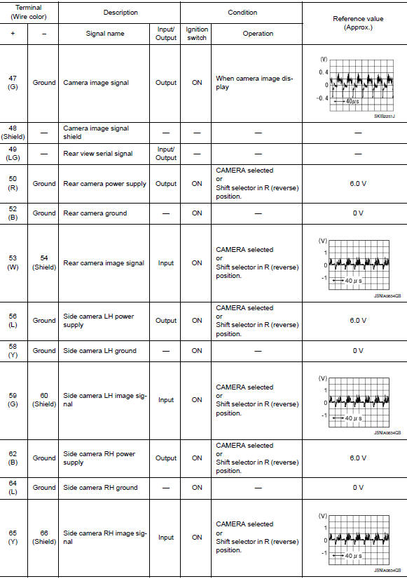
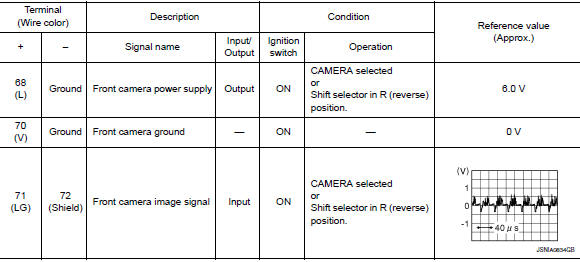
AROUND VIEW MONITOR CONTROL UNIT
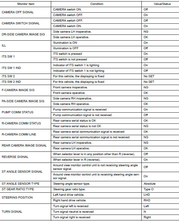
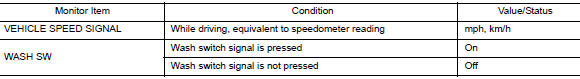
Reference Value
VALUES ON THE DIAGNOSIS TOOL
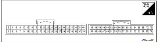
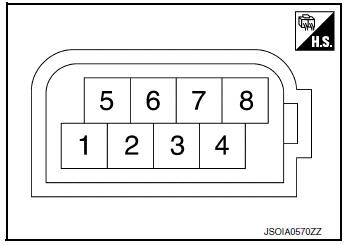
TERMINAL LAYOUT
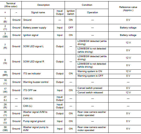
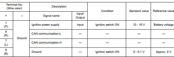
PHYSICAL VALUES
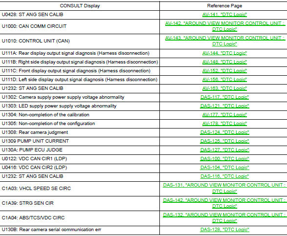
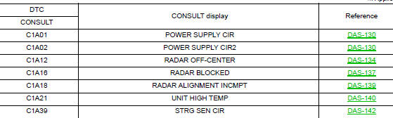
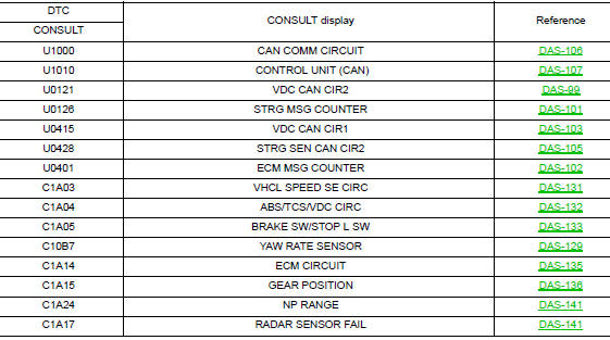
DTC Index
DISTANCE SENSOR
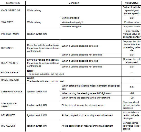
Reference Value
VALUES ON THE DIAGNOSIS TOOL
NOTE: The following table includes information (items) inapplicable to this vehicle. For information (items) applicable to this vehicle, refer to CONSULT display items.
TERMINAL LAYOUT
PHYSICAL VALUES
Fail-safe (Distance Sensor)
If a malfunction occurs in the distance sensor, around view monitor control unit cancels control, sounds a beep, and turns ON the FCW system warning in the information display.
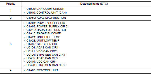
DTC Inspection Priority Chart
If multiple DTCs are detected simultaneously, check them one by one depending on the following DTC inspection priority chart.
DTC Index
REAR VIEW CAMERA WASHER CONTROL UNIT
Reference Value
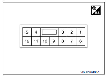
TERMINAL LAYOUT
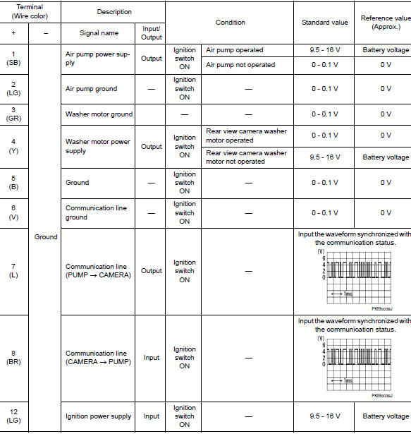
PHYSICAL VALUES
 System description
COMPONENT PARTS
Component Parts Location
View with back door finisher removed
View with glove box assembly removed
View with front bumper removed
View with front bumper remo ...
 Wiring diagram
DRIVER ASSISTANCE SYSTEMS
Wiring Diagram
...
Other materials:
Basic inspection
DIAGNOSIS AND REPAIR WORK FLO
Work Flow
OVERALL SEQUENCE
DETAILED FLOW
1.GET INFORMATION FOR SYMPTOM
Get detailed information from the customer about the symptom (the
condition and the environment when
the incident/malfunction occurs).
Check operation condition of the ...
Precaution
Precaution for Supplemental Restraint System (SRS) "AIR BAG" and "SEAT
BELT
PRE-TENSIONER"
The Supplemental Restraint System such as “AIR BAG” and “SEAT BELT PRE-TENSIONER”,
used along
with a front seat belt, helps to reduce the risk or severity of injury to the
...
P2118 throttle control motor
DTC Description
DTC DETECTION LOGIC
DTC No.
CONSULT screen terms
(Trouble diagnosis content)
DTC detecting condition
P2118
ETC MOT-B1
(Throttle actuator control motor current
range/performance)
ECM detects short in both circuits between ECM and throttle control ...
