Nissan Rogue (T33) 2021-Present Service Manual: Dtc/circuit Diagnosis :: Thigh Support Sensor
Component Function Check
CHECK FUNCTION
 CONSULT
-
Ignition switch ON.
-
Select “Thigh support motor position” in “Data monitor” mode of “DRIVER SEAT”.
-
Check thigh support sensor signal under the following conditions.
| Monitor item | Condition | Status | |
|---|---|---|---|
| Thigh support motor position | Thigh support | Operate (upward) | Change (increase) |
| Operate (downward) | Change (decrease) | ||
| Other than the above | No change | ||
Is the inspection result normal?
YES>>Inspection End.
NO>>Refer to Diagnosis Procedure.
Diagnosis Procedure
CHECK THIGH SUPPORT SENSOR SIGNAL
Check signal between driver seat control unit harness connector and ground with oscilloscope.
| (+) | (-) | Condition |
Signal (Reference value) | ||
|---|---|---|---|---|---|
| Driver seat control unit | |||||
| Connector | Terminal | ||||
| B213 | 15 | Ground | Thigh support | Operate |
|
| Other than the above | 5 V* | ||||
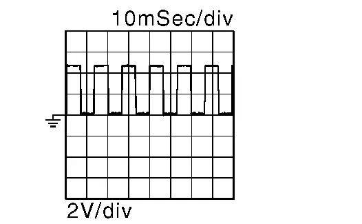
*: When the power consumption control of driver seat control unit is in wake-up state.
Is the inspection result normal?
YES>>Replace driver seat control unit. Refer to Removal and Installation.
NO>>GO TO 2.
CHECK THIGH SUPPORT SENSOR SIGNAL CIRCUIT (OPEN)
-
Ignition switch OFF.
-
Disconnect driver seat control unit connector and thigh support motor LH connector.
-
Check continuity between driver seat control unit harness connector and thigh support motor LH harness connector.
Driver seat control unit Thigh support motor LH Continuity Connector Terminal Connector Terminal B213 15 B221 5 Yes
Is the inspection result normal?
YES>>GO TO 3.
NO>>Repair the harness or connector.
CHECK THIGH SUPPORT SENSOR SIGNAL CIRCUIT (SHORT TO GROUND)
Check continuity between driver seat control unit harness connector and ground.
| Driver seat control unit | (—) | Continuity | |
|---|---|---|---|
| Connector | Terminal | ||
| B213 | 15 | Ground | No |
Is the inspection result normal?
YES>>GO TO 4.
NO>>Repair the harness or connector.
CHECK THIGH SUPPORT SENSOR POWER SUPPLY VOLTAGE
-
Connect driver seat control unit connector.
-
Check voltage between thigh support motor LH harness connector and ground.
(+) (-) Voltage
(Approx.)Thigh support motor LH Connector Terminal B221 2 Ground Battery voltage
Is the inspection result normal?
YES>>GO TO 7.
NO>>GO TO 5.
CHECK THIGH SUPPORT SENSOR POWER SUPPLY CIRCUIT (OPEN)
-
Disconnect driver seat control unit connector.
-
Check continuity between thigh support motor LH harness connector and driver seat control unit harness connector.
Thigh support motor LH Driver seat control unit Continuity Connector Terminal Connector Terminal B221 2 B213 34 Yes
Is the inspection result normal?
YES>>GO TO 6.
NO>>Repair the harness or connector.
CHECK THIGH SUPPORT SENSOR POWER SUPPLY CIRCUIT (SHORT TO GROUND)
Check continuity between thigh support motor LH harness connector and ground.
| Thigh support motor LH | (—) | Continuity | |
|---|---|---|---|
| Connector | Terminal | ||
| B221 | 2 | Ground | No |
Is the inspection result normal?
YES>>Replace driver seat control unit. Refer to Removal and Installation.
NO>>Repair the harness or connector.
CHECK THIGH SUPPORT SENSOR GROUND CIRCUIT (OPEN)
-
Disconnect driver seat control unit connector.
-
Check continuity between thigh support motor LH harness connector and driver seat control unit harness connector.
Thigh support motor LH Driver seat control unit Continuity Connector Terminal Connector Terminal B221 4 B213 33 Yes
Is the inspection result normal?
YES>>Replace seat cushion frame. Refer to Disassembly and Assembly.
NO>>Repair the harness or connector.
Other materials:
U2454-87 Can Comm Circuit
Without Propilot Assist 2.1
DTC Description
CAN COMMUNICATIONCAN (Controller Area Network) is a
serial communication line for real time applications. It is an on-Nissan
Ariya vehicle multiplex communication line with high data communication
speed and excellent error detection ability. Mode ...
P14a7 Charge Air Cooler Cooling Electric Water Pump
DTC Description
DTC DETECTION LOGIC DTC
CONSULT screen terms
(Trouble diagnosis content)
DTC detection condition
P14A7
Charge air cooler cooling electric W/P
(Charge air cooler cooling electric water pump)
Diagnosis condition
Engine running at idle
Warm-up conditio ...
C107c-53 Not Configuration
DTC Description
DTC DETECTION LOGIC DTC No.
CONSULT screen terms
(Trouble diagnosis content) DTC detection condition
C107C
53
Not configuration
(Not configuration)
Diagnosis condition
When ignition switch is ON.
When the power supply voltage is normal.
Signa ...