Nissan Rogue (T33) 2021-Present Service Manual: Driver Assistance System :: Removal and Installation
Front Camera Unit
Without Propilot Assist 2.1
Exploded View

 |
Front camera unit bracket |  |
Front camera unit |  |
Front camera cover |
 |
Metal clip |  |
Pawl |
Removal and Installation
REMOVAL
CAUTION:
-
Do not remove front camera unit bracket and front camera cover from windshield glass.
-
Front camera unit bracket and front camera cover must be replaced together with windshield glass as an assembly.
-
When replacing front camera unit, perform “ADDITIONAL SERVICE WHEN REPLACING FRONT CAMERA UNIT." Refer to Work Procedure.
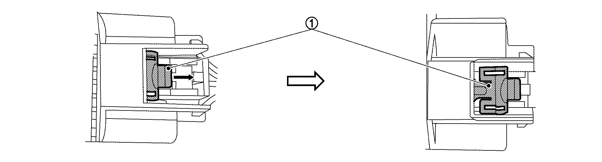
Remove front camera cover.
Release the lock as shown by the arrow in the figure and disconnect the harness connector from the front camera unit.
Using a suitable tool, remove the claw  and remove the front camera unit from the front camera unit bracket
  .
.
INSTALLATION
Installation is in the reverse order of removal.
CAUTION:
-
Be sure to perform "ADDITIONAL SERVICE WHEN REPLACING FRONT CAMERA UNIT" when replacing front camera unit. Refer to Work Procedure.
-
Do not touch or shock front camera lens area or drop front camera unit.
-
Perform camera aiming every time the front camera unit is removed and installed. Refer to Work Procedure.
With Propilot Assist 2.1
Removal and Installation
REMOVAL
Remove luggage side lower finisher LH. Refer to Removal and Installation.
Unbolt and reposition the brake power backup unit. Refer to Exploded View.
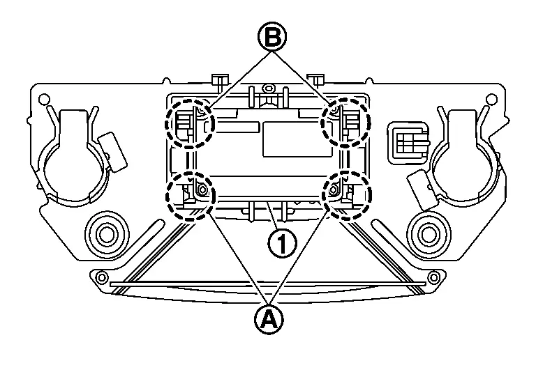
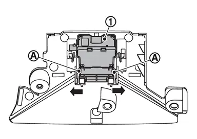
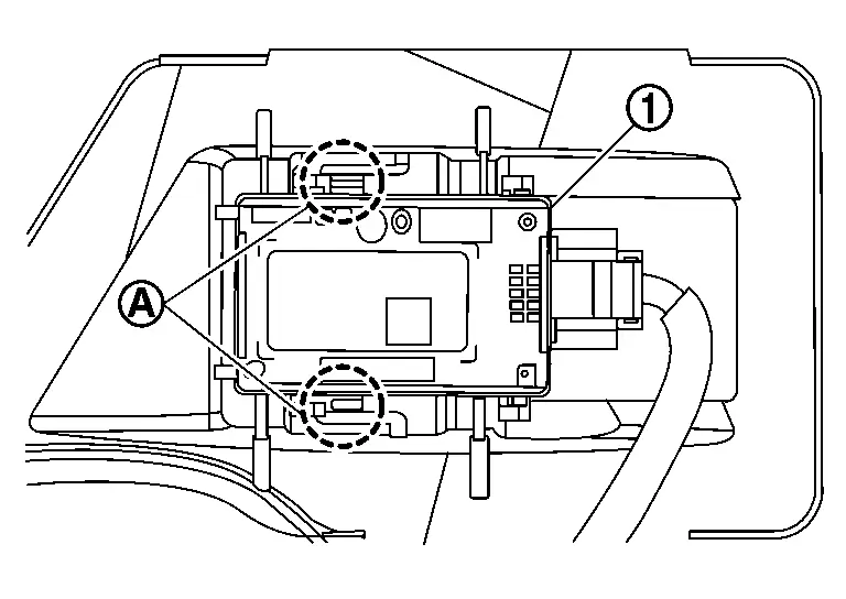
Remove the harness retainer (B) from the front camera unit (1).
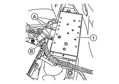
Disconnect the harness connectors (A) from the front camera unit.
Remove bolts and remove the front camera unit.
INSTALLATION
Installation is in the reverse order of removal.
CAUTION:
-
To operate the system normally, perform the following operations when the front camera unit is replaced.
-
Be sure to perform "ADDITIONAL SERVICE WHEN REPLACING FRONT CAMERA UNIT" when replacing front camera unit. Refer to Work Procedure.
-
Driver Assistance Camera
Exploded View
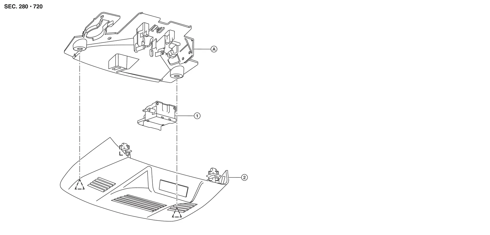
| 1. | Driver assistance camera | 2. | Front camera cover | A. | Driver assistance camera bracket |
|
: Metal clip |  |
: Clip |
Removal and Installation
REMOVAL
CAUTION:
-
Do not remove driver assistance camera bracket from windshield glass.
-
Driver assistance camera bracket must be replaced with windshield glass as an assembly.
-
When replacing driver assistance camera, perform “ADDITIONAL SERVICE WHEN REPLACING FRONT CAMERA UNIT." Refer to Work Procedure.
Remove front camera cover.
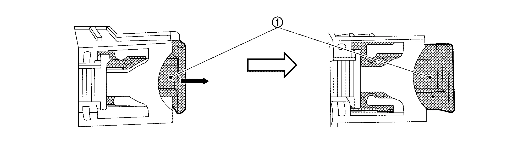
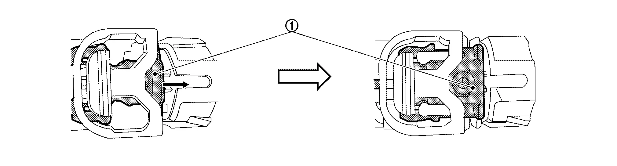
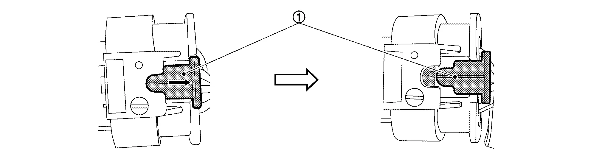
Release the lock (1) as shown and disconnect the harness connector from the front camera unit.
Press tabs (A) on driver assistance camera bracket as shown and remove driver assistance camera (1) from bracket.
INSTALLATION
Installation is in the reverse order of removal.
CAUTION:
-
Be sure to perform "ADDITIONAL SERVICE WHEN REPLACING FRONT CAMERA UNIT" when replacing front camera unit. Refer to Work Procedure.
-
Do not touch or shock driver assistance camera lens area or drop driver assistance camera.
-
Perform camera aiming every time the driver assistance camera is removed and installed. Refer to Work Procedure.
Distance Sensor
Exploded View
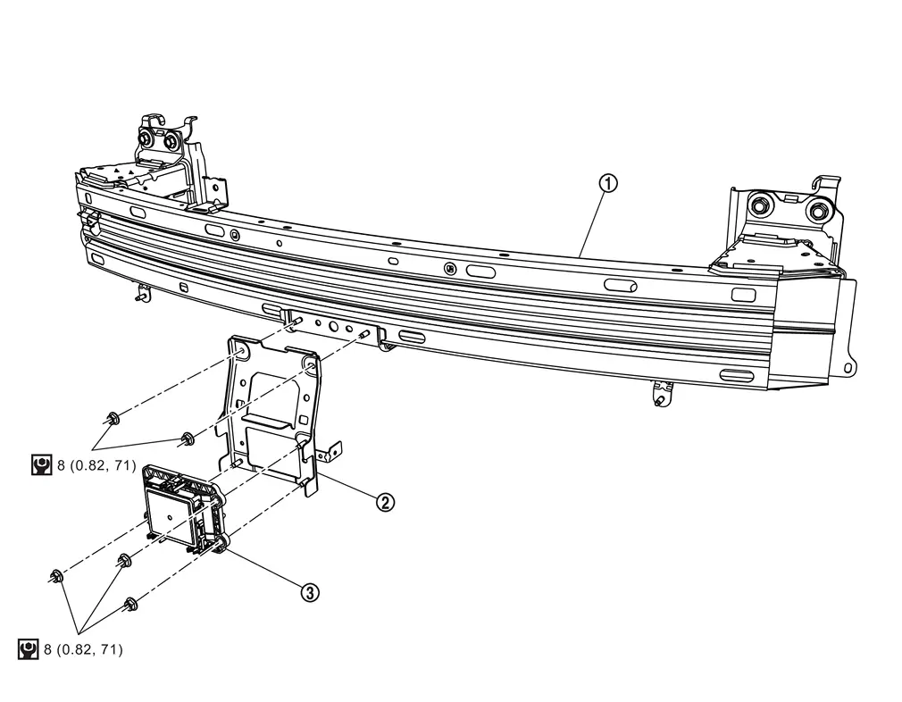
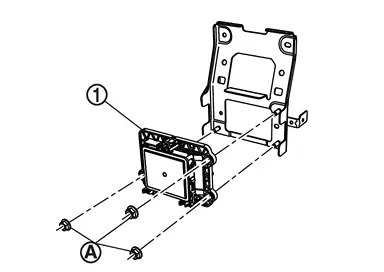
| 1. | Front bumper reinforcement | 2. | Distance sensor bracket | 3. | Distance sensor |
 |
: N·m (kg-m, ft-lb) | — | — | — | — |
Removal and Installation
REMOVAL
Remove front bumper fascia. Refer to Removal and Installation.
Release the lock (1) as shown by the arrow in the figure and disconnect the harness connector from the distance sensor.
Remove nuts (A) and remove distance sensor bracket (1) (if necessary).
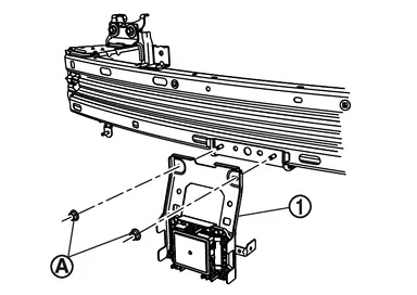
Remove distance sensor nuts (A) and remove distance sensor (1).
INSTALLATION
Installation is in the reverse order of removal.
CAUTION:
-
If distance sensor is being replaced or has been disconnected, perform "ADDITIONAL SERVICE WHEN REPLACING DISTANCE SENSOR". Refer to Work Procedure.
-
Do not touch distance sensor face.
-
Do not drop or shock distance sensor.
-
Make sure distance sensor harness is installed without any twists.
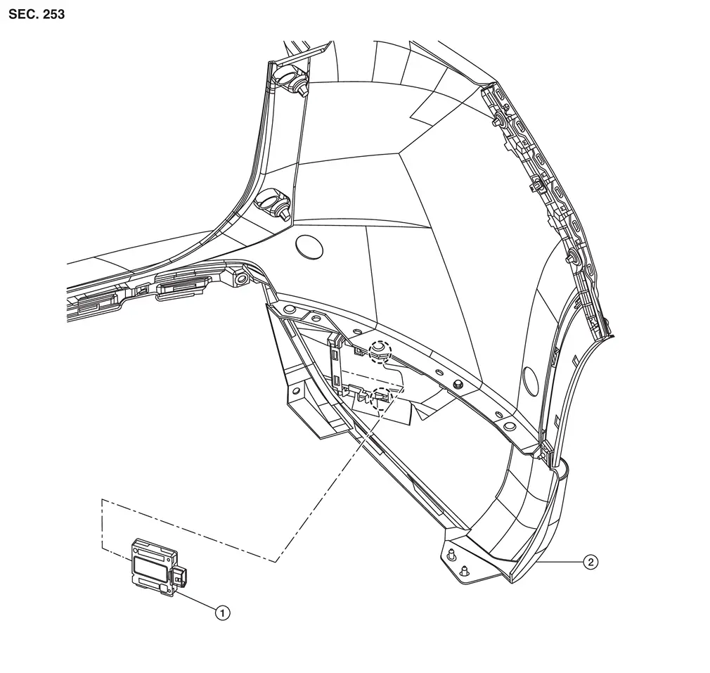
Side Radar
Exploded View
Without ProPILOT Assist 1.1
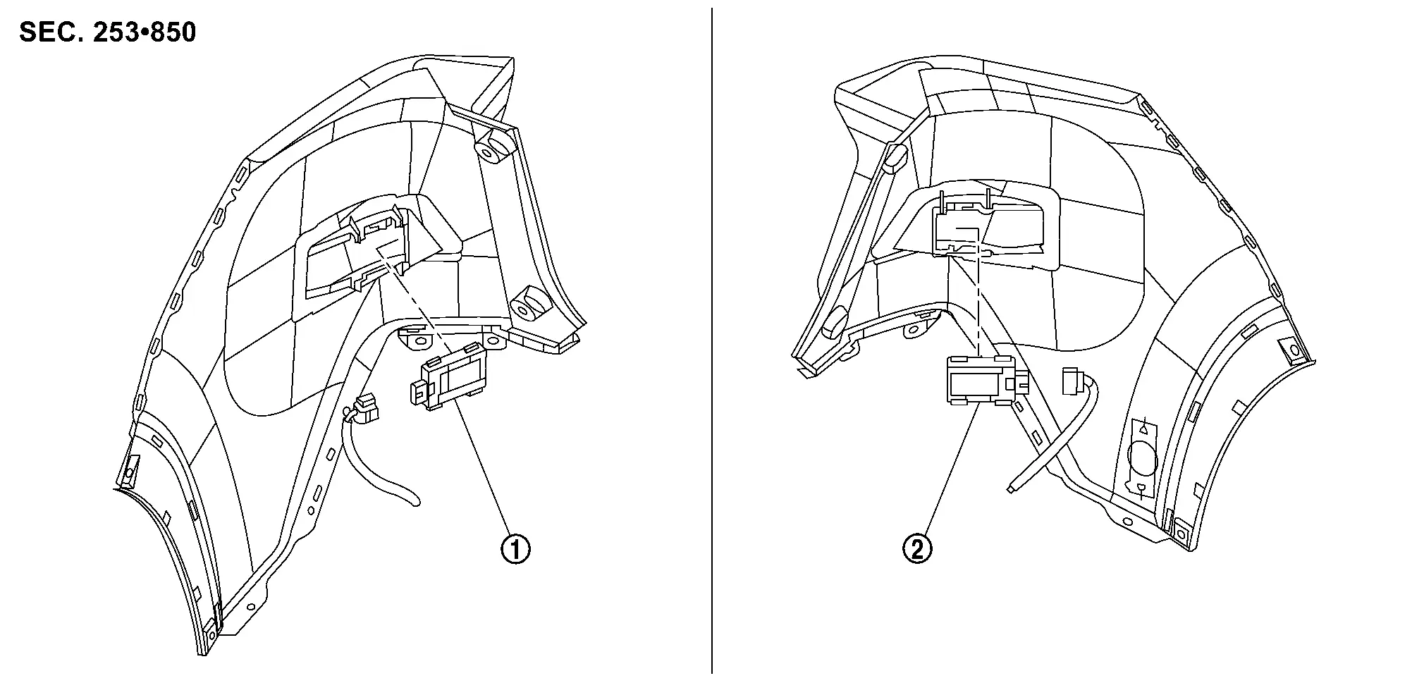
| 1. | Side radar rear (RH) | 2. | Side radar rear (LH) |
With ProPILOT Assist 2.1

| 1. | Front bumper fascia | 2. | Side radar front (LH) | |
Pawl |
 NOTE:
NOTE:
LH shown, RH similar.
| 1. | Side radar rear (LH) | 2. | Rear bumper fascia trim (LH) | |
Pawl |
NOTE:
LH shown, RH similar.
Removal and Installation
Without ProPILOT Assist 2.1
REMOVAL
Remove the rear bumper fascia. Refer to Removal and Installation.
Release the lock as shown by the arrow in the figure and disconnect the harness connector from the side radar rear.
Press the pawls and remove the side radar rear from the side radar bracket.
INSTALLATION
Installation is in the reverse order of removal.
CAUTION:
-
Do not use side radar if lens has flaws.
-
If side radar is being replaced or has been disconnected, perform "ADDITIONAL SERVICE WHEN REPLACING SIDE RADAR". Refer to Work Procedure.
NOTE:
Do not touch side radar lens and keep lens area clean.
With ProPILOT Assist 2.1
FRONT
Reposition wheel and tire.
Remove front spoiler screws (A) and clip (B), and then remove front spoiler.
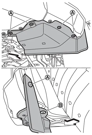
| : Nissan Ariya Vehicle front |
Partially remove and reposition the front half of the front fillet molding. Refer to Exploded View.
Partially remove and reposition the front half of the front fender protector. Refer to Exploded View.
Release the lock (1) as shown and disconnect the harness connector from the side radar front.
Release pawls and remove the side radar front from the side radar front bracket.
Installation is in the reverse order of removal.
CAUTION:
-
Do not use side radar if lens has flaws.
-
If side radar is being replaced or has been disconnected, perform "ADDITIONAL SERVICE WHEN REPLACING SIDE RADAR". Refer to Work Procedure.
NOTE:
Do not touch side radar lens and keep lens area clean.
REAR
Remove the rear bumper fascia. Refer to Removal and Installation.
Release the lock (1) as shown and disconnect the harness connector from the side radar rear.
Release pawls and remove the side radar rear from the side radar bracket.
Installation is in the reverse order of removal.
CAUTION:
-
Do not use side radar if lens has flaws.
-
If side radar is being replaced or has been disconnected, perform "ADDITIONAL SERVICE WHEN REPLACING SIDE RADAR". Refer to Work Procedure.
NOTE:
Do not touch side radar lens and keep lens area clean.
Side Radar Bracket
Exploded View

| 1. | Rear bumper fascia (LH) | 2. | Rear bumper fascia | 3. | Side radar bracket (LH) |
| 4. | Rear bumper fascia trim (LH) |
NOTE:
LH shown, RH similar.
Removal and Installation
REMOVAL
Remove the side radar rear. Refer to Removal and Installation.
Remove the rear bumper fascia trim from the rear bumper fascia. Refer to Exploded View.
INSTALLATION
Install the rear bumper fascia trim (2) to the rear bumper fascia (1). Refer to Exploded View.
CAUTION:
Do not reuse the rear bumper fascia trim.
NOTE:
-
The rear bumper fascia and the rear bumper fascia trim service parts do not include the side radar bracket.
-
LH shown, RH similar.
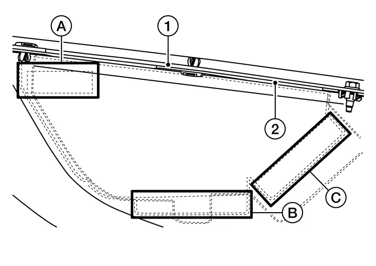
Clean the matching surfaces (A, B, C) on the rear bumper fascia trim thoroughly using 3M K55, K520, or equivalent adhesive promoter.
NOTE:
The matching surfaces on the rear bumper fascia trim service part have molded lines. The side radar bracket service part has tape that will adhere to these matching surfaces.
Remove the double stick tape backing paper (A, B, C) from the side radar bracket (1).
NOTE:
LH shown, RH similar.

Carefully position the side radar bracket on the rear bumper fascia trim using the molded lines. Press firmly on the matching surfaces (A, B, C).
NOTE:
LH shown, RH similar.

Install the side radar rear. Refer to Removal and Installation.
Bsw Indicator
Removal and Installation
REMOVAL
Remove the glass mirror. Refer to Removal and Installation.
NOTE:
Replace the glass mirror if you need to replace the BSW indicator.
INSTALLATION
Installation is in the reverse order of removal.
Steering Vibration Motor
Removal and Installation
REMOVAL
Steering vibration motor is integrated in the steering wheel. Refer to Removal and Installation.
NOTE:
To service steering vibration motor, replace steering wheel.
Driver Monitor Camera
Exploded View
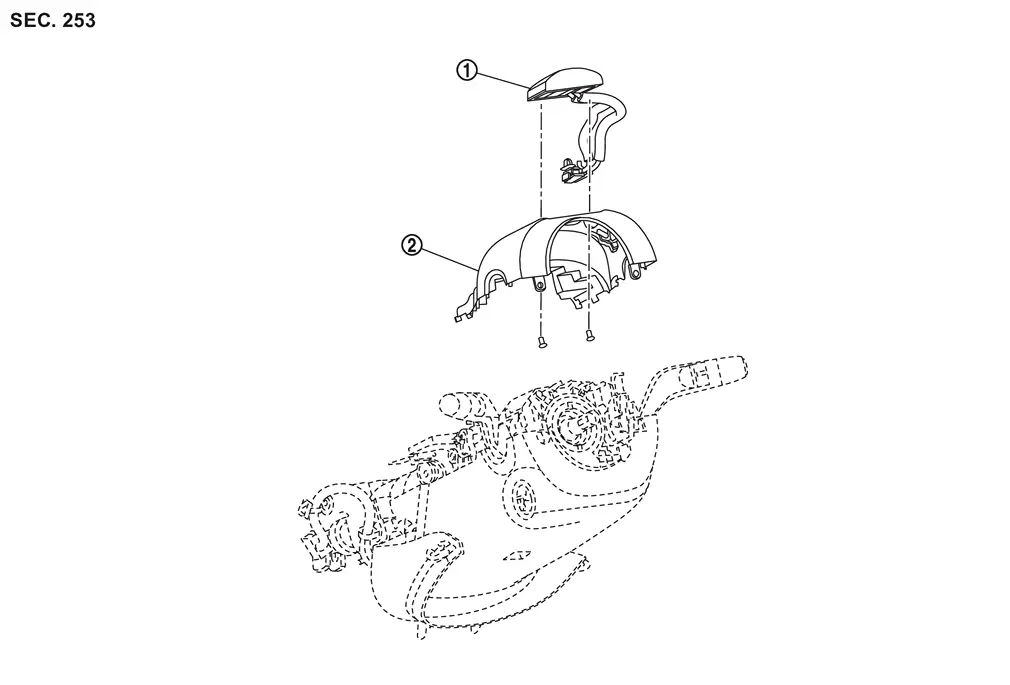
|
Driver monitor camera | |
Steering column cover upper |
Removal and Installation
REMOVAL
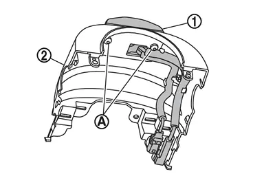
Remove the steering column cover upper. Refer to Exploded View.
Disconnect the driver monitor camera connector.
Remove the screws (A), and remove the driver monitor camera (1) from the steering column cover upper (2).
INSTALLATION
Installation is in the reverse order of removal.
CAUTION:
Make sure that check that the value of "Face" in "DATA MONITOR" of "Driver Monitor Camera" is "In range" after replacing or removing the driver monitor camera. Refer to Work Procedure.
Driver Monitor Camera Control Unit
Removal and Installation
REMOVAL
Remove the instrument panel assembly. Refer to Removal and Installation.
Disconnect the harness connectors from the driver monitor camera control unit.
Remove the nuts and remove the driver monitor camera control unit.
INSTALLATION
Installation is in the reverse order of removal.
CAUTION:
Make sure that check that the value of "Face" in "DATA MONITOR" of "Driver Monitor Camera" is "In range" after replacing or removing the driver monitor camera. Refer to Work Procedure.
Other materials:
Writing of Calibration Data
Work Procedure
DESCRIPTIONIf only the around view monitor control unit
is replaced, the calibration data stored in the camera can be written
to the around view monitor control unit by selecting "Camera
Calibration" of "Work Support" mode in CONSULT.WORK PROCEDUREWRITE CALIBRATION DATA
With C ...
Steering Switch Signal B Circuit
Component Function Check
CHECK COMBINATION METER INPUT SIGNAL
CONSULT
Ignition switch ON.
Select “Steering switch input” in “Data monitor” mode of “M&A”.
Check that the function operates normally according to the following conditions:
Condition Value
CONTRO ...
Symptom Diagnosis. Back Door Auto Closure Function Does Not Operate
Diagnosis Procedure
CHECK DTC WITH AUTOMATIC BACK DOOR CONTROL UNIT
Check that DTC is not detected with automatic back door control unit.
Is the inspection result normal?
YES>>
GO TO 2.
NO>>
Refer to DTC Index.
CHECK OPEN SWITCH
Check open switch.
Refer to DTC Diagnosis Proce ...