Nissan Rogue Service Manual: Component parts
Component Parts Location
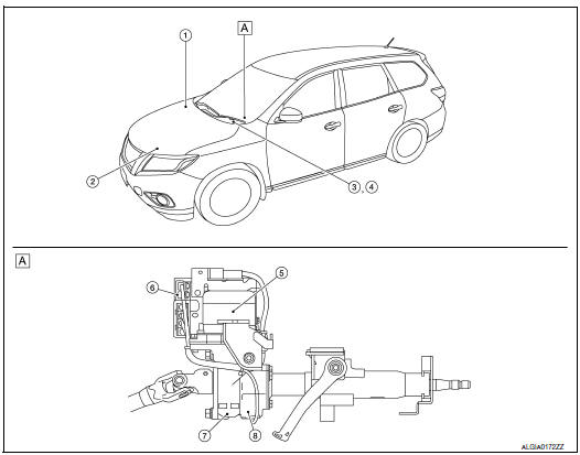
- Steering column assembly
| No. | Component | Function |
| 1 | ABS actuator and electric unit (control unit) |
|
| 2 | ECM |
|
| 3 | Combination meter |
|
|
||
| 4 | EPS warning lamp | STC-7, "EPS SYSTEM : System Description" |
| 5 | EPS motor | STC-6, "EPS Motor, Torque Sensor, Reduction Gear" |
| 6 | EPS control unit | STC-6, "EPS Control Unit" |
| 7 | Reduction gear | STC-6, "EPS Motor, Torque Sensor, Reduction Gear" |
| 8 | Torque sensor | STC-6, "EPS Motor, Torque Sensor, Reduction Gear" |
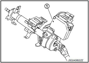
EPS Control Unit
- EPS control unit (1) is installed to steering column assembly.
- EPS control unit performs an arithmetical operation on data, such as steering wheel turning force (sensor signal) from the torque sensor, vehicle speed signal, etc. Then it generates an optimum assist torque signal to the EPS motor according to the driving condition.
- EPS control unit decreases the output signal to EPS motor during continuous extreme use of the power steering function (e.g., full steering) for protection of the EPS motor and EPS control unit (Overload protection control).
EPS Motor, Torque Sensor, Reduction Gear
EPS motor (1), torque sensor (2) and reduction gear (3) are installed to steering column assembly.
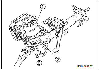
EPS MOTOR
EPS motor provides assist torque in proportion to the control signal from the EPS control unit.
TORQUE SENSOR
Torque sensor detects the steering torque and transmits the signal to the EPS control unit.
REDUCTION GEAR
Reduction gear increases the assist torque provided from the EPS motor, and outputs to the column shaft.

 System
EPS SYSTEM
EPS SYSTEM : System Description
SYSTEM DIAGRAM
INPUT/OUTPUT SIGNAL
Communicates the signal from each control unit via CAN communication.
Control unit
Signal statu ...
Other materials:
Interior room lamp control system
Wiring Diagram
...
Washer switch
Description
Washer switch is integrated with the combination switch.
Combination switch (wiper and washer switch) switches polarity
between front washer operating and rear
washer operating to supply power and ground to the front and rear washer
motor.
Component Inspection
...
Power window motor
DRIVER SIDE
DRIVER SIDE : Description
Door glass moves UP/DOWN by receiving the signal from main power window and
door lock/unlock switch.
DRIVER SIDE : Component Function Check
1. CHECK FRONT POWER WINDOW MOTOR LH OPERATION
Check front power window motor LH operation with main power window a ...
