Nissan Rogue (T33) 2021-Present Service Manual: Component Parts
Nissanconnect with 8" Color Display
Component Parts Location
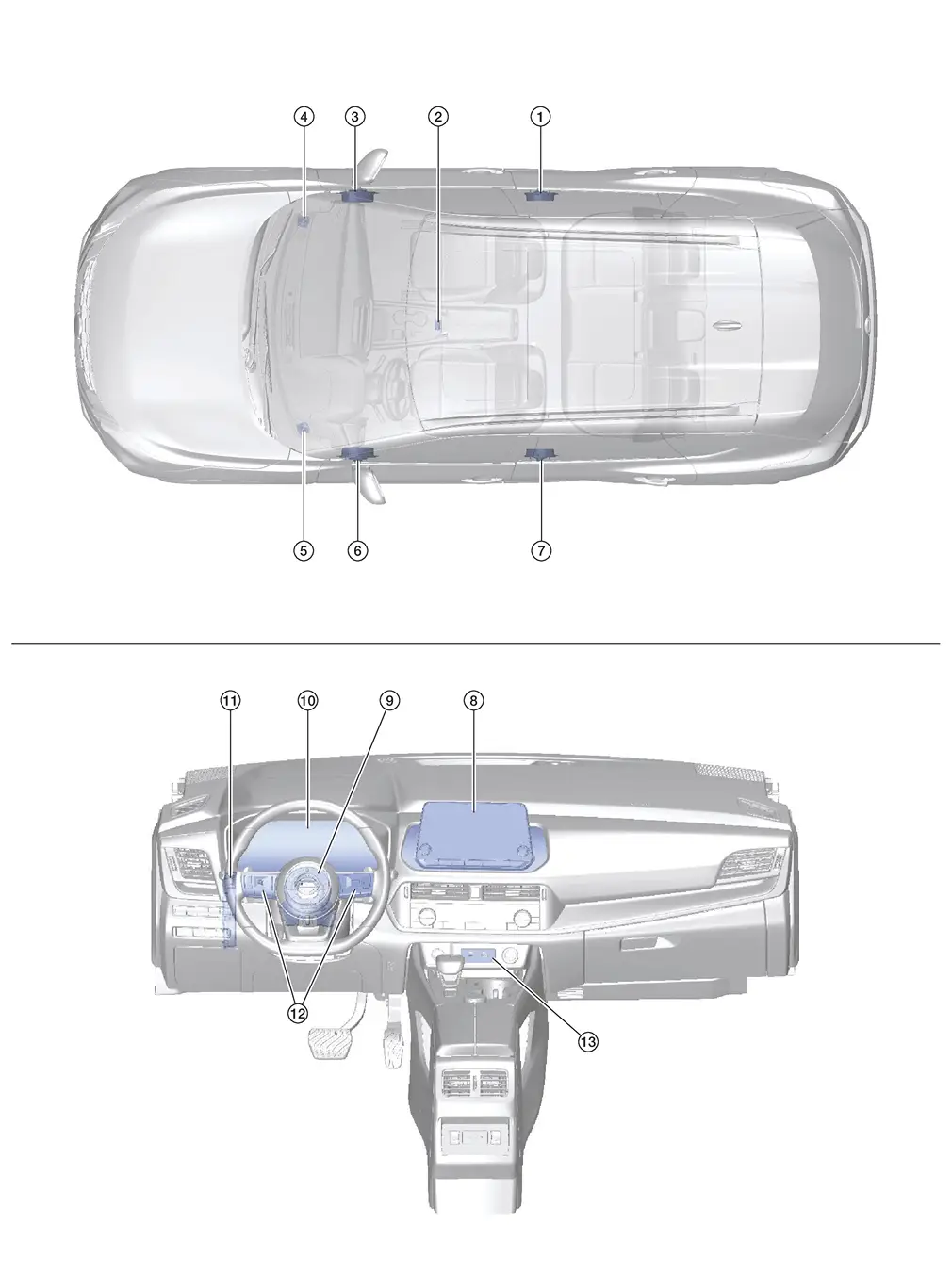
| No. | Component | Function |
|---|---|---|
| 1. | Rear door speaker RH | Refer to Speaker. |
| 2. | Microphone | Refer to Microphone. |
| 3. | Front door speaker RH | Refer to Speaker. |
| 4. | Front speaker RH | |
| 5. | Front speaker LH | |
| 6. | Front door speaker LH | |
| 7. | Rear door speaker LH | |
| 8. | AV control unit | Refer to AV Control Unit. |
| 9. | Spiral cable | Provides a pass-through for the steering switch signals from the steering switches to the combination meter. |
| 10. | Combination meter |
|
| 11. | BCM (Body Control Module) | Provides the AV control unit with the position light request signal via CAN communication. |
| 12. | Steering switches | Refer to Steering Switches. |
| 13. | Front USB media module | Refer to Front USB Media Module. |
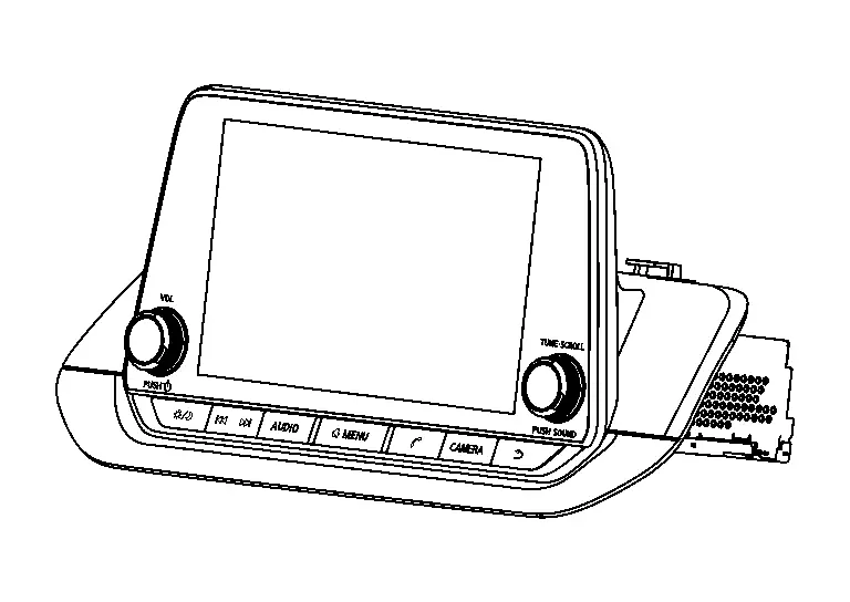
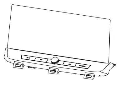
AV Control Unit
-
AV control unit is located in the center of the instrument panel assembly.
-
An 8" display, AM/FM electronic tuner radio, audio amplifier and camera controller are integrated into the AV control unit.
-
The display is a high resolution monitor that includes touch panel functions.
-
Music files stored in a compatible device can be played using one of the separate USB interfaces located in the front auxiliary input jacks.
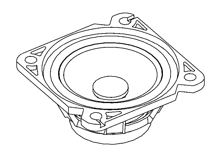
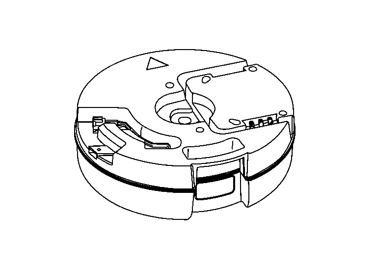
Speaker
FRONT SPEAKER (WITH 6 SPEAKERS)
-
2 in (5.1 cm) speakers are installed in the top corners of the instrument panel assembly.
-
Sound signals generated by the AV control unit output mid range sounds.
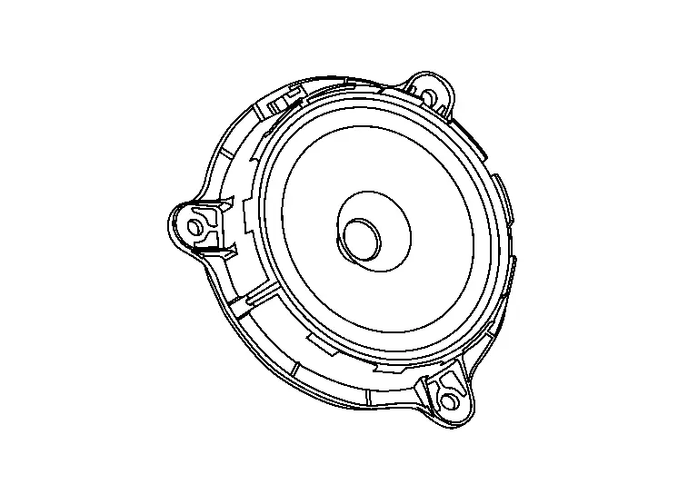
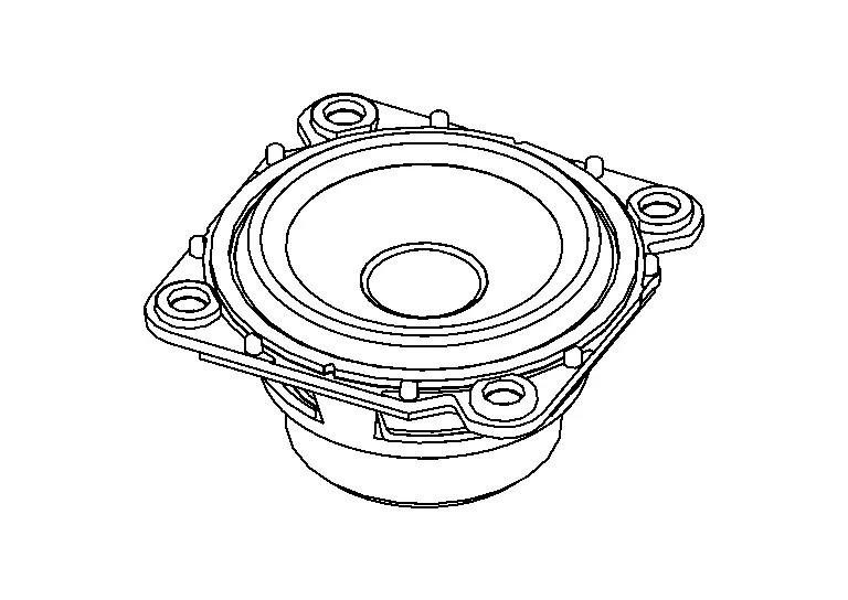
FRONT DOOR SPEAKER
-
6.5 in (16.5 cm) speakers are installed in the front side bottom of the front doors.
-
Sound signals generated by the AV control unit output low and mid range sounds.
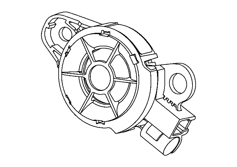
REAR DOOR SPEAKER
-
6.5 in (16.5 cm) speakers are installed in the front side bottom of the rear doors.
-
Sound signals generated by the AV control unit output low and mid range sounds.
Microphone
-
The microphone is installed on the map lamp assembly.

-
The microphone is used for operation of hands-free phone and voice recognition function.
-
The power is supplied from the AV control unit.
Front USB Media Module
-
Front USB media module is located in the front of the console pocket.
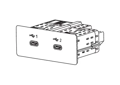
-
An external device can be connected to the AV control unit with a USB cable.
Steering Switches
-
The steering switches are located in the steering wheel.
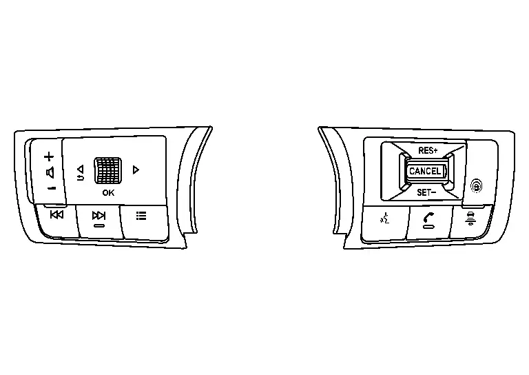
-
Hands-free phone and audio operations can be performed.
-
The steering switches are connected to combination meter.
-
Combination meter transmits steering switch signals to AV control unit via AV communication.
Antenna and Antenna Feeder
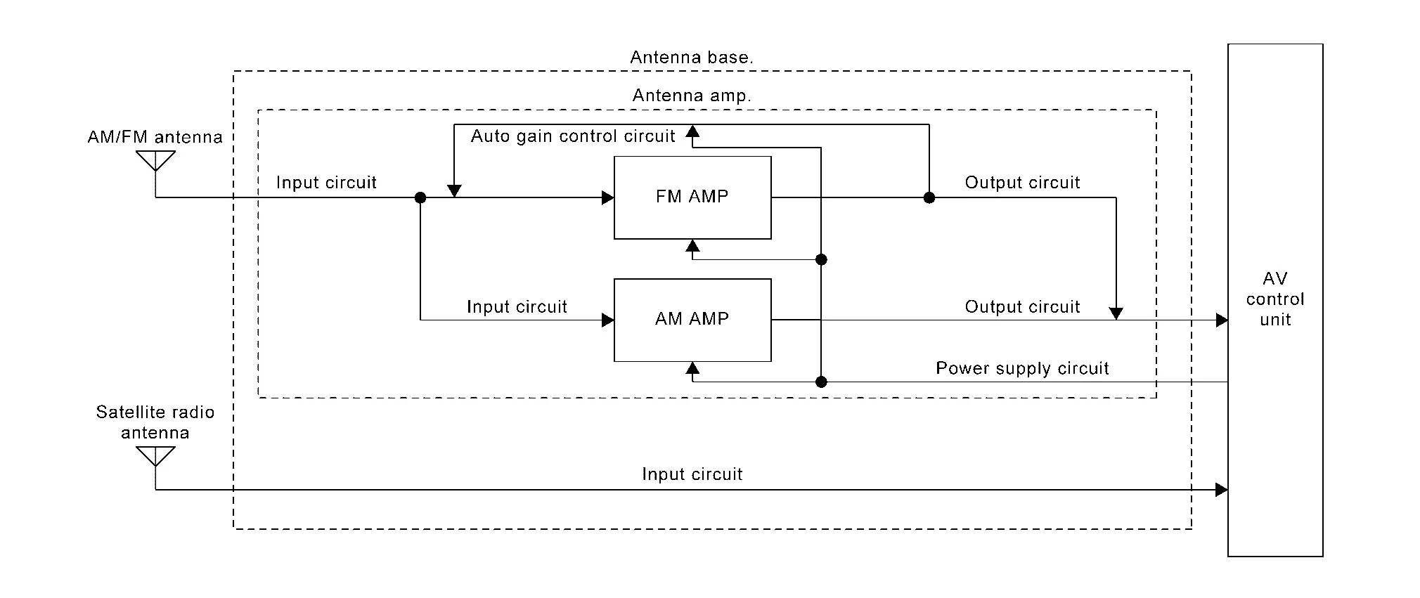
ANTENNA BASE
-
Antenna base is installed on the rear center of the roof.
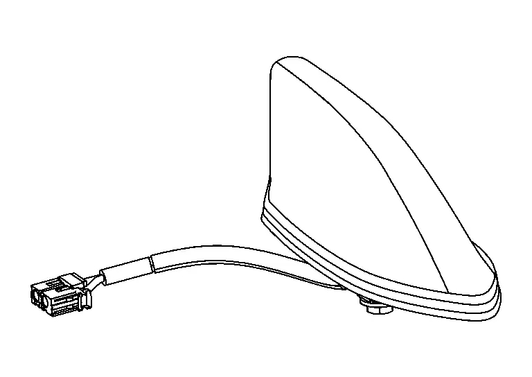
-
Antenna base incorporates the satellite radio antenna, AM/FM antenna and antenna amp.
-
Receives satellite radio waves and outputs them to AV control unit.
-
Receives AM/FM radio waves and outputs them to AV control unit.
-
The AM/FM radio main antenna path has an antenna amp. to obtain sufficient reception power.
ANTENNA FEEDER LAYOUT
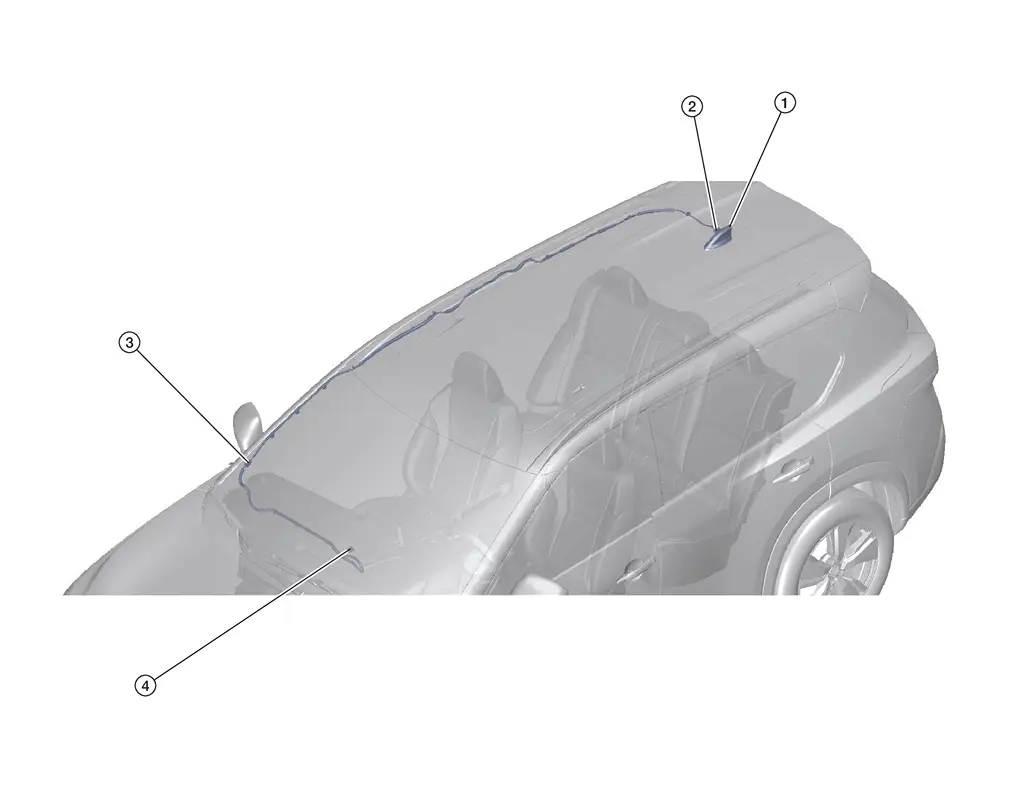
| 1. | Antenna base | 2. | R102 | 3. | M129, R100 |
| 4. | M183, M188 |
Nissanconnect with 12.3" Color Display
Component Parts Location
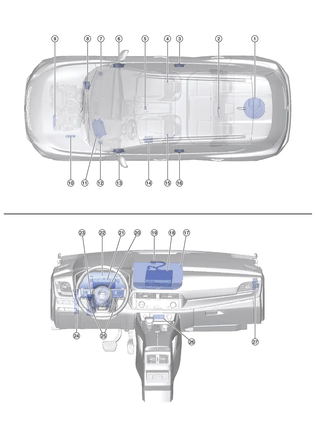
Without Bose
| No. | Component | Function |
|---|---|---|
| 1. | Subwoofer | Refer to Speaker. |
| 2. | Active noise control microphone (Rear) | Refer to Active Noise Control Microphones. |
| 3. | Rear door speaker RH | Refer to Speaker. |
| 4. | Active noise control microphone (Front RH) | Refer to Active Noise Control Microphones. |
| 5. | Microphone | Refer to Microphone. |
| 6. | Front door speaker RH | Refer to Speaker. |
| 7. | Front speaker RH | |
| 8. | ABS (Anti-lock Braking System) actuator and electric unit (control unit) |
Provides the active noise control unit with the following signals via CAN communication:
|
| 9. | TCM (Transmission Control Module) | Provides the active noise control unit with the current gear position signal via CAN communication. |
| 10. | ECM (Engine Control Module) |
Provides the active noise control unit with the following signals via CAN communication:
|
| 11. | Head up display | Refer to Head Up Display Unit. |
| 12. | Front speaker LH | Refer to Speaker. |
| 13. | Front door speaker LH | |
| 14. | Active noise control unit | Refer to Active Noise Control Unit. |
| 15. | Active noise control microphone (Front LH) | Refer to Active Noise Control Microphones. |
| 16. | Rear door speaker LH | Refer to Speaker. |
| 17. | Display unit | Refer to Display Unit. |
| 18. | AV control unit |
|
| 19. | GPS antenna | Refer to Antenna and Antenna Feeder. |
| 20. | Spiral cable | Provides a pass-through for the steering switch signals from the steering switches to the combination meter. |
| 21. | 8CH CAN gateway | Provides routing for the AV communication, CAN communication and ethernet communication signals. |
| 22. | Combination meter |
|
| 23. | Chassis control module (with ProPILOT Assist 2.1) | Provides the active noise control unit with the drive mode signal via CAN communication. |
| 24. | BCM (Body Control Module) |
|
| 25. | Steering switches | Refer to Steering Switches. |
| 26. | Front USB media module | Refer to Front USB Media Module. |
| 27. | Chassis control module (with ProPILOT Assist 1.0) | Provides the active noise control unit with the drive mode signal via CAN communication. |
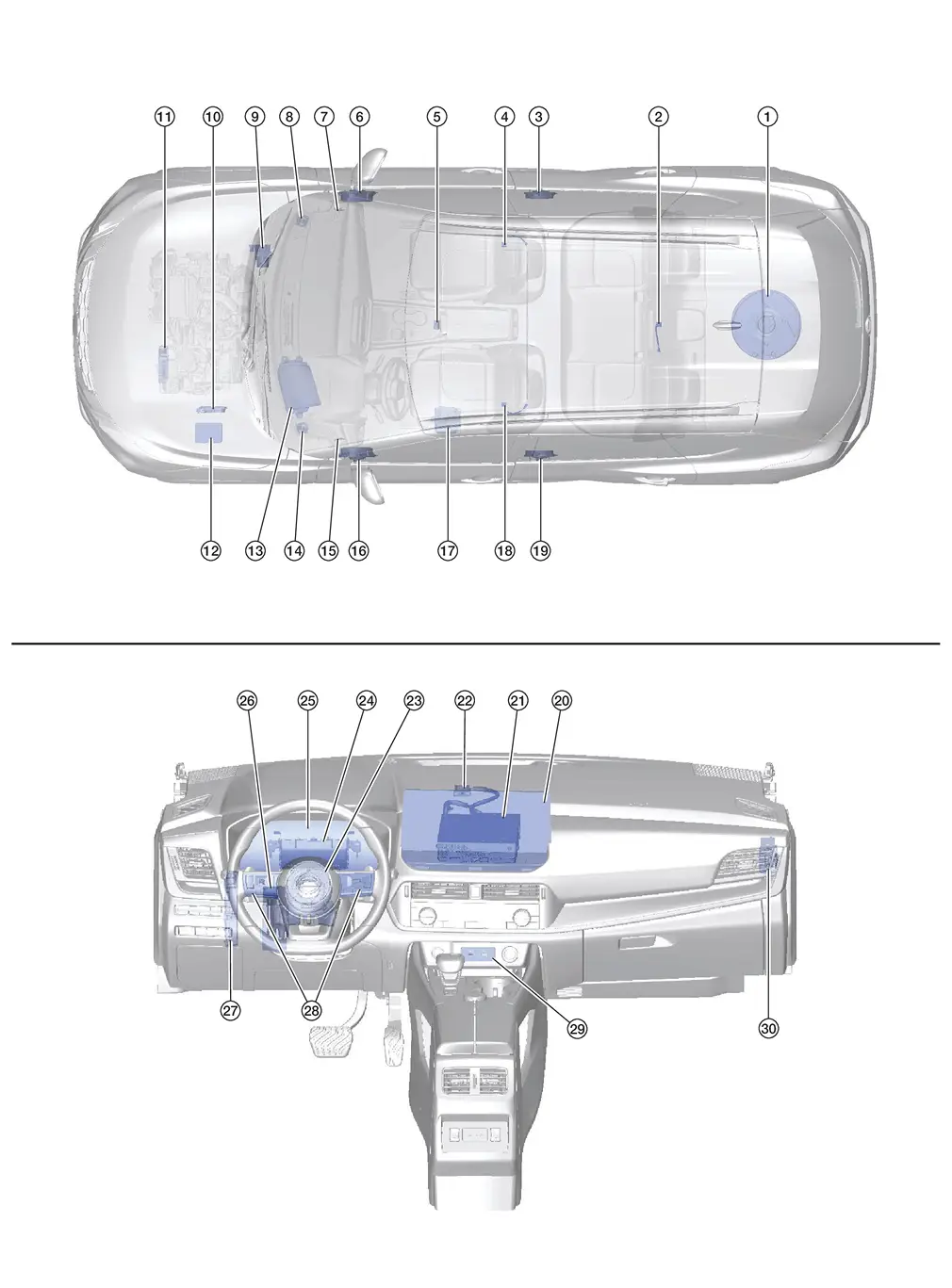
With Bose
| No. | Component | Function |
|---|---|---|
| 1. | Subwoofer | Refer to Speaker. |
| 2. | Active noise control microphone (Rear) | Refer to Active Noise Control Microphones. |
| 3. | Rear door speaker RH | Refer to Speaker. |
| 4. | Active noise control microphone (Front RH) | Refer to Active Noise Control Microphones. |
| 5. | Microphone | Refer to Microphone. |
| 6. | Front door speaker RH | Refer to Speaker. |
| 7. | Front speaker RH | |
| 8. | Instrument panel speaker RH | |
| 9. | ABS (Anti-lock Braking System) actuator and electric unit (control unit) |
Provides the Bose speaker amp. with the following signals via CAN communication:
|
| 10. | ECM (Engine Control Module) |
Provides the Bose speaker amp. with the following signals via CAN communication:
|
| 11. | TCM (Transmission Control Module) | Provides the Bose speaker amp. with the current gear position signal via CAN communication. |
| 12. | IPDM E/R (Intelligent Power Distribution Module Engine Room) | Provides the Bose speaker amp. with the battery voltage signal via CAN communication. |
| 13. | Head up display | Refer to Head Up Display Unit. |
| 14. | Instrument panel speaker LH | Refer to Speaker. |
| 15. | Front speaker LH | |
| 16. | Front door speaker LH | |
| 17. | Bose® speaker amp. | Refer to Bose Speaker Amp.. |
| 18. | Active noise control microphone (Front LH) | Refer to Active Noise Control Microphones. |
| 19. | Rear door speaker LH | Refer to Speaker. |
| 20. | Display unit | Refer to Display Unit. |
| 21. | AV control unit |
|
| 22. | GPS antenna | Refer to Antenna and Antenna Feeder. |
| 23. | Spiral cable | Provides a pass-through for the steering switch signals from the steering switches to the combination meter. |
| 24. | 8CH CAN gateway | Provides routing for the AV communication, CAN communication and ethernet communication signals. |
| 25. | Combination meter |
|
| 26. | Chassis control module (with ProPILOT Assist 2.1) | Provides the Bose speaker amp. with the drive mode signal via CAN communication. |
| 27. | BCM (Body Control Module) |
|
| 28. | Steering switches | Refer to Steering Switches. |
| 29. | Front USB media module | Refer to Front USB Media Module. |
| 30. | Chassis control module (with ProPILOT Assist 1.0) | Provides the Bose speaker amp. with the drive mode signal via CAN communication. |
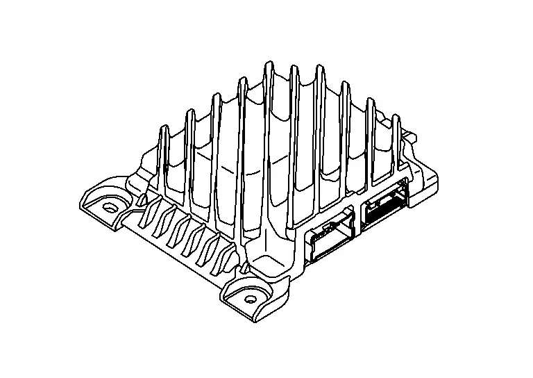
AV Control Unit
-
AV control unit is located behind the display unit.
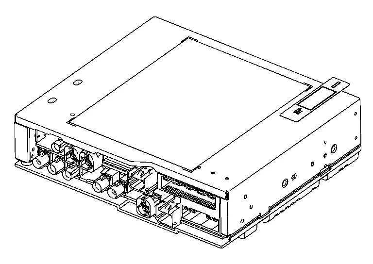
-
AV control unit controls the NissanConnectTM system and integrates the following functions:
Unit equipped AM/FM/HD electronic tuner radio with RDS Camera controller Bluetooth® module WiFi hotspot
Display Unit
-
Display unit is located in the center of cluster lid D.
-
12.3" display image is controlled by AV control unit.
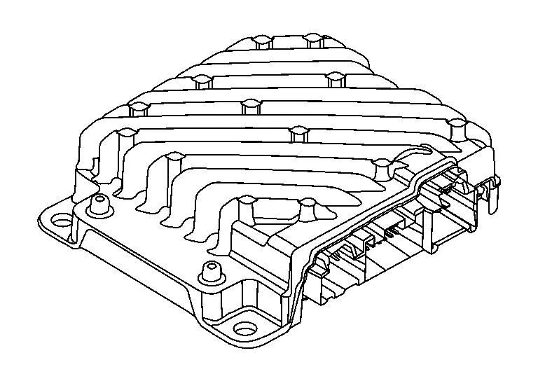
Active Noise Control Unit
-
Active noise control unit is located under the front seat (driver side).
-
Active noise cancellation monitors and measures engine sounds and then uses the speakers to produce acoustically opposing signal to cancel undesirable sounds.
-
Active sound enhancement takes information from the engine and uses digital signal processing to enhance the engine note in the cabin. The technology works with the Nissan Ariya vehicleŌĆÖs sound system to augment or modify the spectrum of select power train sounds in the cabin.
Bose Speaker Amp.
-
Bose speaker amp. is located under the front seat (driver side).
-
Bose speaker amp. receives sound signals from AV control unit and outputs the sound signals to each speaker.
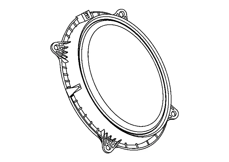
Speaker
WITHOUT BOSE
Front Speaker
-
2 in (5.1 cm) speakers are installed in the top corners of the instrument panel assembly.
-
Sound signals generated by the active noise control unit output mid range sounds.
Front Door Speaker
-
6 x 9 in (15.2 x 22.9 cm) speakers are installed in the front side bottom of the front doors.
-
Sound signals generated by the active noise control unit output low range sounds.
Rear Door Speaker
-
6.5 in (16.5 cm) speakers are installed in the front side bottom of the rear doors.
-
Sound signals generated by the AV control unit output low and mid range sounds.
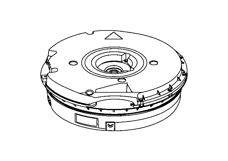
Subwoofer
-
Subwoofer is installed in the spare tire under the luggage floor board.
-
Sound signals generated by the active noise control unit output active noise cancellation antiphase sounds.
WITH BOSE
Instrument Panel Speaker
-
2.5 in (6.1 cm) speakers are installed in the top corners of the instrument panel assembly.
-
Sound signals generated by the Bose speaker amp. output mid range sounds.
Front Speaker
-
1 in (2.5 cm) speakers are installed in the front pillar garnish.
-
Sound signals generated by the Bose speaker amp. output high range sounds.
Front Door Speaker
-
6 x 9 in (15.2 x 22.9 cm) speakers are installed in the front side bottom of the front doors.
-
Sound signals generated by the Bose speaker amp. output low range sounds.
Rear Door Speaker
-
5.25 in (13.33 cm) speakers are installed in the front side bottom of the rear doors.

-
Sound signals generated by the Bose speaker amp. output mid range sounds.
Subwoofer
-
Subwoofer is installed in the spare tire under the luggage floor board.
-
Sound signals generated by the Bose speaker amp. output low range sounds.
Microphone
-
The microphone is installed on the map lamp assembly.
-
The microphone is used for operation of hands-free phone and voice recognition function.
-
The power is supplied from the AV control unit.
Active Noise Control Microphones
-
The active noise control microphones are installed on the front LH, front RH and rear center of the headlining assembly.
-
The active noise control microphones are used for the active noise cancellation system.
-
Power is supplied from the active noise control unit.
Front USB Media Module
-
Front USB media module is located in the front of the console pocket.
-
An external device can be connected to the AV control unit with a USB cable.
Steering Switch
-
The steering switches are located in the steering wheel.
-
Hands-free phone and audio operations can be performed.
-
The steering switches are connected to combination meter.
-
Combination meter transmits steering switch signals to AV control unit via AV communication.
Antenna and Antenna Feeder
GPS ANTENNA
-
GPS antenna is installed in the instrument panel.
-
Power is supplied from the AV control unit.
-
This antenna amplifies radio waves received from the GPS satellite and transmits the GPS signal to the AV control unit.
 NOTE:
NOTE:
An object on the instrument panel may cause the reception sensitivity to be decreased.
ANTENNA BASE
-
Antenna base is installed on the rear center of the roof.
-
Antenna base incorporates the satellite radio antenna, AM/FM antenna and antenna amp.
-
Receives satellite radio waves and outputs them to AV control unit.
-
Receives AM/FM radio waves and outputs them to AV control unit.
-
The AM/FM radio main antenna path has an antenna amp. to obtain sufficient reception power.
ANTENNA FEEDER LAYOUT

| 1. | Antenna base | 2. |
R104, R105 (with ProPILOT Assist 2.1) R102 (without ProPILOT Assist 2.1) |
3. | M129, R100 |
| 4. | M142, M165, M190 | 5. | GPS antenna |
Other materials:
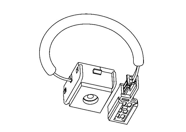
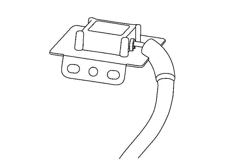
Ignition Coil with Power Transistor
Component Inspection
CHECK IGNITION COIL WITH POWER TRANSISTOR-1
Turn ignition switch OFF.
Disconnect ignition coil harness connector.
Check resistance between ignition coil terminals as per the following.
Ignition coil
Condition
Resistance
+
ŌłÆ
Terminal
1 ...
P2253 Ho2s2
DTC Description
To judge malfunctions, the diagnosis checks that the A/F signal
computed by ECM from the A/F sensor 1 signal fluctuates according to
fuel feedback control.DTC DETECTION LOGIC DTC
CONSULT screen terms
(Trouble diagnosis content)
DTC detection condition
P2253
00
...
Dtc/circuit Diagnosis. U1327-52 Mac Key Update
DTC Description
DTC DETECTION LOGIC DTC No.
CONSULT screen items
(Trouble diagnosis content) DTC Detection Condition
U1327-52
MAC key update
(Message authentication code key update)
Diagnosis condition
-
Signal (terminal)
-
Threshold
MAC key writing is incomplete. ...