Nissan Rogue Service Manual: Component parts
CVT CONTROL SYSTEM
CVT CONTROL SYSTEM : Component Parts Location
- Engine room, LH
- Transaxle assembly
| No. | Component | Function | |
| 1 | Combination meter | Mainly transmits the following signal to TCM via CAN communication.
Mainly receives the following signals from TCM via CAN communication.
Refer to MWI-6, "METER SYSTEM : Component Parts Location" for detailed installation location. |
|
| 2 | ABS actuator and electric unit (control unit) | Mainly transmits the following signal to TCM via CAN communication.
Refer to BRC-8, "Component Parts Location" for detailed installation location. |
|
| 3 | ECM | Mainly transmits the following signal to TCM via CAN communication.
Mainly receives the following signals from TCM via CAN communication.
Refer to EC-14, "Component Parts Location" for detailed installation location. |
|
| 4 | BCM | Mainly transmits the following signal to TCM via CAN communication.
|
|
| 5 | SPORT mode switch | DMS-4, "SPORT Mode Switch" | |
| 6 | Overdrive control switch | TM-19, "CVT CONTROL SYSTEM : Overdrive Control Switch" | |
| 7 | TCM | TM-13, "CVT CONTROL SYSTEM : TCM" | |
| 8 | Transmission range switch | TM-14, "CVT CONTROL SYSTEM : Transmission Range Switch" | |
| 9 | Input speed sensor | TM-15, "CVT CONTROL SYSTEM : Input Speed Sensor" | |
| 10 | CVT unit connector |
— |
|
| 11 | Control valve | CVT fluid temperature sensor* | TM-16, "CVT CONTROL SYSTEM : CVT Fluid Temperature Sensor" |
| Primary pressure sensor* | TM-16, "CVT CONTROL SYSTEM : Primary Pressure Sensor | ||
| Secondary pressure sensor* | TM-16, "CVT CONTROL SYSTEM : Primary Pressure Sensor | ||
| Line pressure solenoid valve* | TM-18, "CVT CONTROL SYSTEM : Line Pressure Solenoid Valve" | ||
| Primary pressure solenoid valve* | TM-17, "CVT CONTROL SYSTEM : Primary Pressure Solenoid Valve" | ||
| Secondary pressure solenoid valve* | TM-18, "CVT CONTROL SYSTEM : Secondary Pressure Solenoid Valve" | ||
| Torque converter clutch solenoid valve* | TM-18, "CVT CONTROL SYSTEM : Torque Converter Clutch Solenoid Valve" | ||
| Select solenoid valve* | TM-18, "CVT CONTROL SYSTEM : Select Solenoid Valve" | ||
| 12 | Primary speed sensor | TM-14, "CVT CONTROL SYSTEM : Primary Speed Sensor" | |
| 13 | Output speed sensor | TM-15, "CVT CONTROL SYSTEM : Output Speed Sensor" | |
*: These components are included in control valve assembly.
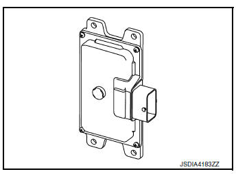
CVT CONTROL SYSTEM : TCM
- The TCM consists of a microcomputer and connectors for signal input and output and for power supply.
- The vehicle driving status is judged based on the signals from the sensors, switches, and other control units, and the optimal transaxle control is performed.
- For TCM control items, refer to TM-31, "CVT CONTROL SYSTEM : System Description".
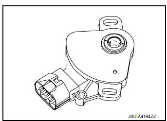
CVT CONTROL SYSTEM : Transmission Range Switch
- The transmission range switch is installed to upper part of transaxle case.
- The transmission range switch detects the selector lever position.
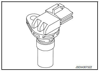
CVT CONTROL SYSTEM : Primary Speed Sensor
- The primary speed sensor is installed to side cover of transaxle.
- The primary speed sensor detects primary pulley speed.
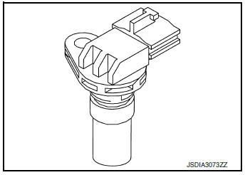
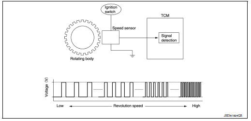
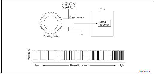
- The primary speed sensor generates an ON-OFF pulse signal according to the rotating body speed. TCM judges the rotating body speed from the pulse signal.
CVT CONTROL SYSTEM : Output Speed Sensor
- The output speed sensor is installed to back side of transaxle.
- The output speed sensor detects final gear speed.
- The output speed sensor generates an ON-OFF pulse signal according to the rotating body speed. TCM judges the rotating body speed from the pulse signal.
CVT CONTROL SYSTEM : Input Speed Sensor
- The input speed sensor is installed to the front side of transaxle case.
- The input speed sensor detects input shaft speed.
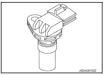
- The input speed sensor generates an ON-OFF pulse signal according to the rotating body speed. TCM judges the rotating body speed from the pulse signal.
CVT CONTROL SYSTEM : CVT Fluid Temperature Sensor
- The CVT fluid temperature sensor is installed to control valve.
- The CVT fluid temperature sensor detects CVT fluid temperature in oil pan.
- The fluid temperature sensor uses a thermistor, and changes the signal voltage by converting changes in the CVT fluid temperature to a resistance value. TCM evaluates the CVT fluid temperature from the signal voltage value.
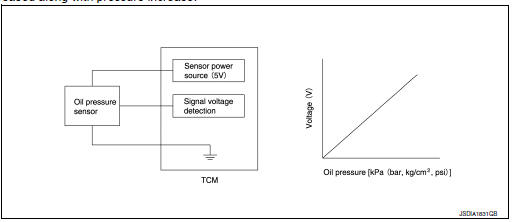
CVT CONTROL SYSTEM : Primary Pressure Sensor
- The primary pressure sensor is installed to control valve.
- The primary pressure sensor detects the pressure applied to the primary pulley.
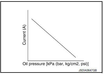
- When pressure is applied to the ceramic device in the primary pressure sensor, the ceramic device is deformed, resulting in voltage change. TCM evaluates the primary pressure from its voltage change. Voltage is increased along with pressure increase.
CVT CONTROL SYSTEM : Secondary Pressure Sensor
- The secondary pressure sensor is installed to control valve.
- The secondary pressure sensor detects the pressure applied to the secondary pulley.
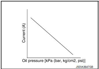
- When pressure is applied to the metal diaphragm in the secondary pressure sensor, the metal diaphragm is deformed, resulting in voltage change. TCM evaluates the secondary pressure from its voltage change. Voltage is increased along with pressure increase.
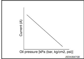
CVT CONTROL SYSTEM : Primary Pressure Solenoid Valve
- The primary pressure solenoid valve is installed to control valve.
- The primary pressure solenoid valve controls the primary reducing valve. For information about the primary reducing valve, refer to TM-27, "TRANSAXLE : Component Description".
- The primary pressure solenoid valve uses the linear solenoid valve [N/H (normal high) type].
NOTE:
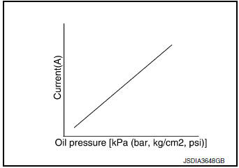
- The principle of the linear solenoid valve utilizes the fact that the force pressing on the valve spool installed inside the coil increases nearly in proportion to the current. This allows it to produce a fluid pressure that is proportional to this pressing force.
- The N/H (normal high) produces hydraulic control when the coil is not energized.

CVT CONTROL SYSTEM : Secondary Pressure Solenoid Valve
- The secondary pressure solenoid valve is installed to control valve.
- The secondary pressure solenoid valve controls the secondary reducing valve. For information about the secondary reducing valve, refer to TM-27, "TRANSAXLE : Component Description".
- The secondary pressure solenoid valve uses the linear solenoid valve [N/H (normal high) type].
NOTE:
- The principle of the linear solenoid valve utilizes the fact that the force pressing on the valve spool installed inside the coil increases nearly in proportion to the current. This allows it to produce a fluid pressure that is proportional to this pressing force.
- The N/H (normal high) produces hydraulic control when the coil is not energized.
CVT CONTROL SYSTEM : Select Solenoid Valve
- The select solenoid valve is installed to control valve.
- The select solenoid valve adjusts the forward clutch engaging pressure and the reverse brake engaging pressure. For information about the forward clutch and reverse brake, refer to TM-27, "TRANSAXLE : Component Description".
- The select solenoid valve uses the linear solenoid valve [N/H (normal high) type].
NOTE:
- The principle of the linear solenoid valve utilizes the fact that the force pressing on the valve spool installed inside the coil increases nearly in proportion to the current. This allows it to produce a fluid pressure that is proportional to this pressing force.
- The N/H (normal high) type produces hydraulic control when the coil is not energized.
CVT CONTROL SYSTEM : Torque Converter Clutch Solenoid Valve
- The torque converter clutch solenoid valve is installed to control valve.
- The torque converter clutch solenoid valve controls the torque converter clutch control valve. For information about the torque converter clutch control valve, refer to TM-27, "TRANSAXLE : Component Description".
- The torque converter clutch solenoid valve utilizes a linear solenoid valve [N/L (normal low) type].
NOTE:
- The principle of the linear solenoid valve utilizes the fact that the force pressing on the valve spool installed inside the coil increases nearly in proportion to the current. This allows it to produce a fluid pressure that is proportional to this pressing force.
- The N/L (normal low) type does not produce hydraulic control when the coil is not energized.
CVT CONTROL SYSTEM : Line Pressure Solenoid Valve
- The line pressure solenoid valve is installed to control valve.
- The line pressure solenoid valve controls the pressure regulator valve. For information about the pressure regulator valve, refer to TM-27, "TRANSAXLE : Component Description".
- The line pressure solenoid valve uses the linear solenoid valve [N/ H (normal high) type].
NOTE:
- The principle of the linear solenoid valve utilizes the fact that the force pressing on the valve spool installed inside the coil increases nearly in proportion to the current. This allows it to produce a fluid pressure that is proportional to this pressing force.
- The N/H (normal high) produces hydraulic control when the coil is not energized.
CVT CONTROL SYSTEM : Overdrive Control Switch
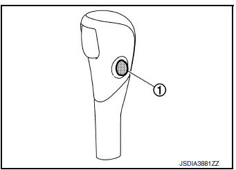
- The overdrive control switch 1 is installed to the shift selector knob.
- When the O/D OFF indicator lamp on the combination meter is OFF and the overdrive control switch is pressed, the O/D OFF is active and the O/D OFF indicator lamp is ON.
- When the O/D OFF indicator lamp on the combination meter is ON and the overdrive control switch is pressed, the O/D OFF is cancelled and the O/D OFF indicator lamp is OFF
CVT CONTROL SYSTEM : O/D OFF Indicator Lamp
DESIGN/PURPOSE
The O/D OFF indicator lamp notifies the driver that the shift control of transaxle is in O/D OFF.
BULB CHECK
For two seconds after the ignition switch is turned ON.
SYSTEM DIAGRAM
SIGNAL PATH
- When overdrive control switch signal is input to the combination meter, the combination meter transmits the overdrive control switch signal to the TCM via CAN communication.
- When all of the following conditions are satisfied, the TCM transmits OD OFF indicator lamp signal to the combination meter via CAN communication. The combination meter turns ON the O/D OFF indicator lamp on the combination meter, according to the signal.
- TCM receives overdrive control switch via CAN communication from combination meter.
- Selector lever: D position.
LIGHTING CONDITION
When all of the following conditions are satisfied.
- Ignition switch: ON
- Selector lever: D position
- Overdrive control switch is pressed when the O/D OFF indicator lamp is OFF.
SHUTOFF CONDITION
When any of the conditions listed below is satisfied.
- Ignition switch: Other than ON
- Overdrive control switch is pressed when the O/D OFF indicator lamp is ON.
- Selector lever is shifted to other than D position when the O/D OFF indicator lamp is ON.
CVT CONTROL SYSTEM : Shift Position Indicator
TCM transmits shift position signal to combination meter via CAN communication. The actual shift position is displayed on combination meter according to the signal.
SHIFT LOCK SYSTEM
SHIFT LOCK SYSTEM : Component Parts Location
- Brake pedal, upper
- CVT shift selector assembly
COMPONENT DESCRIPTION
| No. | Component | Function |
| 1 | BCM | When the stop lamp switch signal is input to the BCM, the BCM
outputs the shift lock solenoid
operating signal.
Refer to BCS-7, "BODY CONTROL SYSTEM : Component Parts Location" for detailed installation location. |
| 2 | Stop lamp switch |
|
| 3 | Park position switch | The park position switch detects that the selector lever is in “P” position. |
| 4 | Shift lock solenoid | The shift lock solenoid operates according to the signal from the BCM and moves the lock lever. |

 Structure and operation
TRANSAXLE
TRANSAXLE : Cross-Sectional View
Converter housing
Oil pump
Planetary gear
Control valve
Oil pan
Steel belt
Primary pulley
Secondary pulley
Side cover
Transa ...
Other materials:
Remote keyless entry system (if so equipped)
WARNING
Radio waves could adversely affect
electric medical equipment. Those who
use a pacemaker should contact the
electric medical equipment manufacturer
for the possible influences before
use.
The remote keyless entry keyfob transmits
radio waves ...
Rear door finisher
Exploded View
Rear door
Rear power window switch finisher
Rear door screw cover
Rear door inside handle finisher
Rear door finisher
Tether clip
Tether
Pawl
Clip
Removal and Installation
REMOVAL
Remove screw cover (1).
Remo ...
Air cleaner filter
Exploded view
Mass air flow sensor
Air cleaner filter
Air cleaner case (lower)
Air duct assembly
Grommet
Resonator bracket (front)
Resonator bracket (rear)
Resonator
Air duct
Mounting clip
Air duct assembly
Air duct assembly
...
